background image

ECHO PELLET E.I. II 

PELLET HEATER 


12 

WALL & REMOTE THERMOSTAT 
INSTALLATION FOR ECHO E.I.  

The  wall  thermostat  is  designed  to  automatically 
regulate the room temperature by shutting the stove 
on  and  off  or  changing  the  output  from  High  to 
Low.  Remember  to  leave  the  control  knob  on  the 
High  or  Medium  position  when  utilizing  the  wall 
thermostat feature. 

A  wall  or  remote  thermostat  can  be  hooked  to  run 
the Echo 3000 E.I. automatically. The following is a 
step-by-step  procedure  for  installing  the  optional 
thermostat.  Note  connection  terminals  on  the 
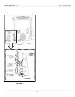
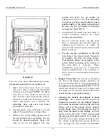
bottom  right  side  of  the  unit  (see  FIGURE  8).  Use 
18/2 thermostat wire for installation.  

1.


UNPLUG HEATER FROM WALL OUTLET 

2.


Hook  up  the  thermostat  wires  to  terminals  (see 
FIGURE  8).  Remove  copper  shunt.  Replace 
shunt if thermostat hook-up is disconnected. If a 
remote thermostat is used, mount the “receiver” 
to the bottom of the stove with Velcro and then 
hook  up  receiver  wires  to  the  terminal  (see 
FIGURE  8).  Follow  thermostat  manufacturer’s 
instructions. 

3.


Locate  thermostat  approximately  10  to  12  feet 
from  heater  or  in  an  area  that  requires  steady 
temperature.  Run  thermostat  wires  from  heater 
to  thermostat  along  wall  or  under  carpet,  etc., 
and  hook  wires  to  thermostat  terminals. 
Designate  a  central  location  that  will  maintain 
room temperature and leave remote in that area. 

4.


Make  sure  all  wiring  is  complete  before 
plugging the Echo back into the wall outlet. 

 5.  The thermostat can run the stove either ON/OFF 

or  HI/Low.  Factory  setting  is  ON/OFF. 
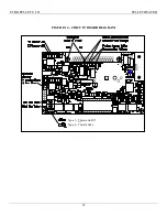
Changing the Type setting jumper on the circuit 
board  will  switch  to  the  Hi/Low  mode  (see 
FIGURE 15).  This should be done in extremely 
cold climates so the house will maintain an even 

temperature  and  not  be  cycling  on/off  
constantly. 

6.  Be  aware  that  the  life  of  the  igniter  is     affected 

by  the  ash  build  up  in  the  fire  pot  and  the 
number  of  times  the  stove  is  cycling  on/off.    If 
more  than  four  or  five  times  a  day  then  you 
should switch to  the Hi/Low mode.  Check fire 
pot frequently for ash build up. 

IMPORTANT:  Any  electrical  work  performed  on 
the  Echo  should  be  done  by  qualified  personnel. 

Always plug AC cord in before DC battery


Summary of Contents for Echo Pellet E.I. II

Page 1: ...ALLATION INSPECTION AND PERMIT REQUIREMENTS FAILURE TO COMPLY WITH OWNER S MANUAL INSTRUCTIONS WILL VOID WARRANTY AND COULD RESULT IN PROPERTY DAMAGE BODILY INJURY OR EVEN DEATH PLEASE LEAVE THIS MANU...

Page 2: ...Light 16 Hopper clean out 18 filling 14 Igniter Removal 28 Installation 7 battery 16 clean out tee 7 distance to openings 7 floor protection 7 pipe configuration 8 pipe connections 11 venting requirem...

Page 3: ...ure 3 7 Figure 4 8 Figure 5 9 Figure 6 10 Figure 7 11 Figure 8 13 Figure 9 14 Figure 10 14 Figure 11 15 Figure 12 18 Figure 13 Replacement Parts List 21 Figure 14 Circuit Board Diagram 22 Figure 15 El...

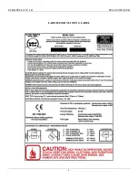
Page 4: ...ECHO PELLET E I II PELLET HEATER 4 LABORATORY LISTING LABEL...

Page 5: ...d container of ashes should be placed on a non combustible floor or the ground well away from all combustible materials pending final disposal If the ashes are disposed of by burial in soil or otherwi...

Page 6: ...ustion and ventilation air The air inlet must remain unrestricted while unit is in use Outside air connection is made at the air intake located on the rear of the stove see Figure 2 The Outside Air Ki...

Page 7: ...e hearth pad must be used if installed on a carpet wood floor or other comb ustible material see FIGURE 3 Maintain 6 152mm beyond the front and beyond each side of the fuel loading and ash removal ope...

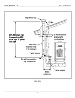
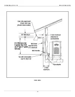
Page 8: ...ECHO PELLET E I II PELLET HEATER 8 FIGURE 4...

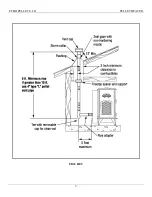
Page 9: ...ECHO PELLET E I II PELLET HEATER 9 FIGURE 5...

Page 10: ...ECHO PELLET E I II PELLET HEATER 10 FIGURE 6...

Page 11: ...ar cleaning see FIGURE 4 Whenever the pipe run in any installation is 10 feet or more the use of 4 inch Type L vent pipe is required Horizontal runs must be limited to 2 feet On vertical runs on an ex...

Page 12: ...mostat manufacturer s instructions 3 Locate thermostat approximately 10 to 12 feet from heater or in an area that requires steady temperature Run thermostat wires from heater to thermostat along wall...

Page 13: ...ECHO PELLET E I II PELLET HEATER 13 FIGURE 8...

Page 14: ...9 Use good quality pellets that give a vibrant yellow flame with little or no soot Poor quality pellets will burn rich with black sooty smoke and ash will accumulate quickly IMPORTANT The quality of p...

Page 15: ...nsure the built in thermostat terminals on the bottom of the stove are used See FIGURE 8 It is recommended the heater is run on High for approximately 30 minutes to get the heat exchanger hot before t...

Page 16: ...k draft If there is problem with the fan guard becoming blocked due to dust and lint build up then this light will come on and stay steady red The feed will shut off and the stove will shut down when...

Page 17: ...he automatic ignition feature will not work on DC power only The automatic ignition feature will not work on DC power only Contact your Dealer for manual start instructions MAINTENANCE PROCEDURES CAUT...

Page 18: ...d every four to six weeks or whenever the Clean mode on the Control Panel is utilized a Fly ash can also accumulate in the vent pipe Inspect the exhaust system frequently to maintain free flow of exha...

Page 19: ...E POWER OFF empty the hopper and check the feed chute to see what is causing the jam ENSURE THE POWER IS OFF Remove any foreign material or object and restart the heater CAUTION Keep fingers and hands...

Page 20: ...ian If the fly ash build up is excessive try another pellet brand In most climates the pellets and fly ash can absorb moisture from the air and create creosote and a severe clogging problem The heater...

Page 21: ...ECHO PELLET E I II PELLET HEATER 21 FIGURE 13 REPLACEMENT PARTS LIST...

Page 22: ...ECHO PELLET E I II PELLET HEATER 22 FIGURE 14 CIRCUIT BOARD DIAGRAM Type 2 Thermo Hi Lo Type 1 Thermo On Off...

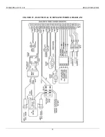
Page 23: ...ECHO PELLET E I II PELLET HEATER 23 FIGURE 15 ELECTRICAL SCHEMATIC WIRING DIAGRAM 250 VAC 250 VAC...

Page 24: ...heat exchanger tubes both sides using a pellet vac or shop vac CAUTION Do not use a household vacuum cleaner 4 Connect vinyl clean out tube to pellet vac or shop vac An adaptor must be used to connec...

Page 25: ...ue high temp safety sensor that will shut the stove off if there is a down draft blocked flue or high temperature condition If installing the stove on the side of the house that is hit by prevailing w...

Page 26: ...ECHO PELLET E I II PELLET HEATER 26 APPENDIX B E I FIREPOT ASSEMBLY...

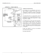
Page 27: ...re 2 The Air Intake Damper control located on the air intake module see FIGURE 2 regulates the amount of combustion air being fed to the pellet fire pot For example a high vertical run of pipe over 10...

Page 28: ...ECHO PELLET E I II PELLET HEATER 28 APPENDIX D IGNITER REMOVAL...

Page 29: ...amages so the above limitation or exclusion may not apply to you This warranty gives you specific legal rights that vary from state to state WARRANTY WORK If you find this unit to be defective in mate...

Page 30: ...ECHO PELLET E I II PELLET HEATER...

Reviews: