ECHO PELLET E.I. II
PELLET HEATER
7
INSTALLATION
1.
When deciding on the location of your heater
and vent pipe, minimize the alteration and
reframing of structural components of the
building. Vent pipe must be installed so that
access is provided for inspection and cleaning.
2.
Avoid installing heater in high-traffic areas.
Keep children well away from heater when in
operation.
3.
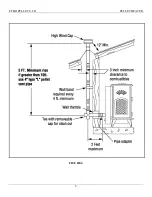
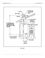
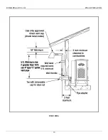
A 3-inch clearance to combustibles must be
maintained for horizontal and vertical
venting
. When passing through ceilings or
walls, a listed wall thimble must be used,
making sure all combustible materials and
insulation products are a minimum of 3 inches
away from the pellet vent pipe. If using the
Pellet Pro, a 1” clearance is required.
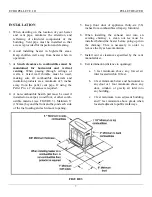
4.
A non-combustible hearth pad must be used if
installed on a carpet, wood floor, or other comb-
ustible material (see FIGURE 3). Maintain 6”
(152mm) beyond the front and beyond each side
of the fuel loading and ash removal opening.
5.
Keep front door of appliance thirty-six (36)
inches from combustibles (drapery, furniture).
6.
When installing the exhaust vent into an
existing chimney, a clean out tee must be
installed behind the heater before going up into
the chimney. This is necessary in order to
remove the fly ash accumulation.
7.
Install vent at clearances specified by the vent
manufacturer.
8.
Exit termination (distance to openings):
a.
3 feet minimum above any forced air
inlet located within 10 feet.
b.
4 feet minimum below and horizontal to
any door or 1 foot minimum above any
door, window, or gravity air inlet into
any building.
c.
2 feet minimum to an adjacent building
and 7 feet minimum above grade when
located adjacent to public walkways.
FIGURE 3
5”
3”
Summary of Contents for Echo Pellet E.I. II
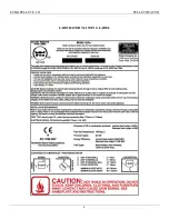
Page 4: ...ECHO PELLET E I II PELLET HEATER 4 LABORATORY LISTING LABEL...
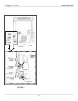
Page 8: ...ECHO PELLET E I II PELLET HEATER 8 FIGURE 4...
Page 9: ...ECHO PELLET E I II PELLET HEATER 9 FIGURE 5...
Page 10: ...ECHO PELLET E I II PELLET HEATER 10 FIGURE 6...
Page 13: ...ECHO PELLET E I II PELLET HEATER 13 FIGURE 8...
Page 21: ...ECHO PELLET E I II PELLET HEATER 21 FIGURE 13 REPLACEMENT PARTS LIST...
Page 26: ...ECHO PELLET E I II PELLET HEATER 26 APPENDIX B E I FIREPOT ASSEMBLY...
Page 28: ...ECHO PELLET E I II PELLET HEATER 28 APPENDIX D IGNITER REMOVAL...


