background image


Hardware Manual COMBILOG 1020 

130


11.8 MODBUS-Protocol 
11.8.1 

Transmission Sequence 

 
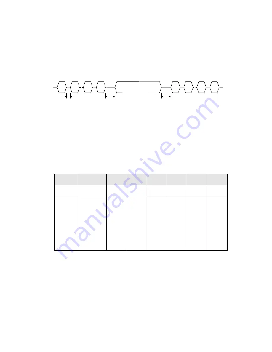
The data are transmitted from and to the datalogger with follow-
ing sequence:


SD

..

..

ED

SD  .. .. .. .. .. .. .. .. ..  ED

request telegram

response telegram

T

1

request telegram

T

2

T

3

SD

..

..

ED


T1:  time between two characters 
T2:  time between request-telegram corresponding response-telegram 
T3:  time between response-telegram and next request-telegram 


Minimum and maximum appearing values for periods T1, T2 and 
T3 and the adjustment ranges are given in table 11.14. 


protocol  baud rate  T1 min T1 max T2 min T2 max T3 min  T3 max

adjustable 

no no yes no no yes 

2400 bps 

4800 bps 

9600 bps 

19200 bps 

38400 bps 

1,5 CT 3,5 CT

T2min 

1.2 


3,5 CT 

0.1 to 

600 sec


Table 11.14    Values and adjustment range for periods T1, T2 and T3 


(CT: character time:  1 CT = character length [bit] / baud rate [bps]) 


Summary of Contents for COMBILOG 1020

Page 1: ...COMBILOG 1020 Datalogger Hardware Manual Version 3 09...

Page 2: ...Hardware Manual COMBILOG 1020 2 Issue 03 11 2005 Technical data are subject to change...

Page 3: ...e of Theodor Friedrichs products Theodor Friedrichs products are not designed intended or authorized for use as components and medical systems or other applications indeed to support or sustain life o...

Page 4: ...Hardware Manual COMBILOG 1020 4...

Page 5: ...DESCRIPTION 15 3 INSTALLATION 22 4 SIGNAL PROCESSING 32 5 FUNCTIONAL DESCRIPTION 40 6 DISPLAY MENU OPERATION 67 7 DATA STORAGE 78 8 MASTER FUNCTION 84 9 INITIATION AND TEST 87 10 STRUCTURE OF THE BUS...

Page 6: ...Hardware Manual COMBILOG 1020 6...

Page 7: ...PTION 15 2 1 System Overview 15 2 2 Range of Application 16 2 3 Features 17 2 4 Configration Software 21 3 INSTALLATION 22 3 1 Mounting Fixing 22 3 2 Protective System 22 3 3 Ambient Temperature 23 3...

Page 8: ...ocessing 35 4 5 Scan Rate and power consumption 38 4 6 Signal Processing 39 5 FUNCTIONAL DESCRIPTION 40 5 1 Analog Input Channel 41 5 2 Digital Input Channel 51 5 3 Digital Output Channel 58 5 4 Arith...

Page 9: ...N 84 8 1 Master function 84 9 INITIATION AND TEST 87 9 1 Before Connecting the Device 87 9 2 After Connecting the Device 87 9 3 Configuration of the Datalogger 87 10 STRUCTURE OF THE BUS TOPOLOGY 89 1...

Page 10: ...8 MODBUS Protocol 130 11 9 Sample Program 143 11 10 Autocall Function 144 11 11 Modem Connection 146 12 SPECIFICATIONS 147 12 1 Power Supply 147 12 2 Signal Inputs Outputs 147 12 3 Signal Processing...

Page 11: ...Sensors at the Datalogger 156 C Pinout Arrangements for Analog Sensors of Th Friedrichs 157 D Pinout Arrangements for digital Sensors of Th Friedrichs 158 E Configuration table for the datalogger 159...

Page 12: ...Hardware Manual COMBILOG 1020 12...

Page 13: ...alogger COMBILOG 1020 exclusively in accordance with the notices technical data and operating condi tions mentioned in this manual In case of inexpert handling or wrong application possible disturbanc...

Page 14: ...on in potentially explosive surroun dings EExe EExi These however are not subject of this manual which only explains the general use of the datalogger COMBILOG 1020 1 3 Contact for Inquiries In case o...

Page 15: ...ted Two serial interfaces RS232 and RS485 are built in featuring communication via ASCII PROFIBUS or MODBUS Data storage is achieved by internal RAM or PCMCIA memory card optionally SELECT switch and...

Page 16: ...atalogger COMBILOG 1020 supports measuring methods with 2 3 and 4 wire technique The signal processing required in accordance with the sensors used such as gain linearisation offset correction etc can...

Page 17: ...all functions of the RS485 interface remain available Furthermore the datalogger can send messages in case of user definable conditions automatically via modem or SMS A configuration program is inclu...

Page 18: ...mption Display and Operation LED status key for digital inputs outputs LED status key for malfunction and operation ERR RUN LC display 2 x 16 characters and push turn knob for opera tion Measured Valu...

Page 19: ...igurable measuring rate and averaging interval Configuration on file offline operation Configuration via bus online operation Programming Loading of a new download program Allocation of address and ba...

Page 20: ...ent of thermocouples Master function for data exchange with other modules on the same bus Use of SRAM cards for memory expansion Baud rate up to 38 400 bps 2 versions Standard version with 20 MHz proc...

Page 21: ...automatically Additional sensors can be defined Additional parameters like scan rate averaging interval data re cording error handling automatic message generation master function etc are configurable...

Page 22: ...hen press the datalogger on the DIN rail until the two straps on the top snap in In order to take the datalogger off the DIN rail slide the module lateral off the rail or in case it is not possible li...

Page 23: ...the datalogger COMBILOG 1020 shows follow ing elements ERR RUN TH FRIEDRICHS CO COMBILOG 1020 D I G I T A L A I N 8 A I N 7 A I N 6 A I N 5 A I N 4 A I N 3 A I N 2 A I N 1 A N A L O G SOURCE SELECT In...

Page 24: ...ess rotary knob 13 8 analog inputs 7 Fuse 0 1 A M Table 3 1 Description of the parts on the front of the device Integrated multifuse from serial number 090323 Pin Assignment Terminal Assignment Termin...

Page 25: ...r between terminal and the front of the datalogger Not more than 2 leads should be connected with one clamp In this case the leads should have the same conductor cross sec tion Note Wire connection is...

Page 26: ...RCE In In AGND SOURCE In In AGND SOURCE In In AGND SOURCE In In AGND MEMORY CARD PCMCIA Display 2 x 16 Character COM TX RX B A 0 V 10 18V SUPPLY RS 485 RS 232 I O 1 0 V I O 2 0 V I O 3 I O 4 I O 5 0 V...

Page 27: ...also be remote fed via longer lines Several data loggers can be supplied parallel within the admissible voltage range considering the voltage drop in the lines The supply lines can also be installed...

Page 28: ...r COM TX RX B A 0 V 10 18V SUPPLY RS 485 RS 232 I O 1 0 V I O 2 0 V I O 3 I O 4 I O 5 0 V I O 6 0 V 0 1 AM 0 V 0 V Figure 3 3 Connection of the datalogger to the bus Alternatively the bus can also be...

Page 29: ...O 6 0 V 0 1 AM 0 V 0 V Figure 3 4 Connection of the datalogger to the bus by a stub cable 3 8 Sensor Connection The analog and digital signal inputs and outputs are wired ac cording to measurement ta...

Page 30: ...are not exceeding the values de scribed in the technical data chapter 12 3 9 Several Sensors at one Datalogger The datalogger COMBILOG 1020 can simultaneously receive and process sensor signals from...

Page 31: ...I N 2 A I N 1 SOURCE In In AGND SOURCE In In AGND SOURCE In MEMORY CARD PCMCIA Display 2 x 16 Character ERR RUN TH FRIEDRICHS CO COMBILOG 1020 D I G I T A L A I N 8 A I N 7 A I N 6 A I N 5 A I N 4 A...

Page 32: ...vely They are particularly designed to measure voltages currents and resistances There are 8 equal analog inputs each input can be configured individually Note Overloads of more than 10 VDC will lead...

Page 33: ...tputs are possible The digital inputs have an excess voltage protection transil di odes with nominal threshold 18 V Input voltages between 3 5 VDC and 18 DC are interpreted as logic LOW 0 input volt a...

Page 34: ...erature drift less than 25 ppm K it is recommended to ac complish the measurement via an external shunt with a corre spondingly low temperature coefficient 5 ppm K For this pur pose the input channel...

Page 35: ...with amplifier stages of 100 200 400 800 and 3200 The amplification in alignment with the accuracy and resolution of the calculated measuring values results from the selection of the measuring range w...

Page 36: ...nds 1 2 3 4 5 10 15 20 30 minutes resp 1 2 3 4 6 8 and 12 hours The calculated values are finally stored in the memory The special user program the data for configuration linearization and scaling etc...

Page 37: ...URCE AGND In In SOURCE AGND In In SOURCE AGND In In SOURCE AGND In In SOURCE AGND A D Converter LED RUN LED ERR SELECT Display RTC Treiber MEMORY CARD PCMCIA 12 V TX RX RS 232 Interface COM 0 V I O 1...

Page 38: ...g this mode the datalog ger needs only about 5 mW The average current consumption over a longer time period will be accordingly filter number of used scan rate analog inputs 1 sec 10 sec 60 sec 1 20 m...

Page 39: ...values but does not affect the averaging 4 6 Signal Processing Arithmetical averaging is carried out using several measuring val ues The averaging interval which is the same for all channels can be se...

Page 40: ...hannels can be configured as Analog Input Channel Digital Input Channel Digital Output Channel Arithmetic Channel Setpoint Channel Alarm Channel For each channel various kinds of channel information a...

Page 41: ...vided Voltage measurement Current measurement Resistance measurement Temperature measurement with thermocouples For each of these principles the datalogger COMBILOG 1020 of fers several types of measu...

Page 42: ...tage to be measured is con nected between an analog input In and analog ground AGND Differential measurements are realized by using two analog inputs In and In Measuring range is between 0 and 10 V No...

Page 43: ...RCE In In AGND SOURCE measuring voltage U connection scheme circuit Figure 5 1 Voltage measurement single ended Connection scheme Circuit U2 U1 SOURCE SOURCE AGND In In In In AIN 1 AIN 2 AGND In U U2...

Page 44: ...f an external resis tor which is connected parallel to the current source to the analog signal input and analog ground AGND The power capacity of this external shunt has to be adapted to the current s...

Page 45: ...n AGND SOURCE connection scheme circuit Figure 5 3 Current measurement with internal shunt measuring current I external shunt In I U1 Rext U1 I Rext AGND Rext A I N 2 A I N 1 SOURCE In In AGND SOURCE...

Page 46: ...0 and 20 k Note The datalogger COMBILOG 1020 supports resistance measurement in 2 3 and 4 wire technique With resistance measurement in 2 wire technique the supply lines cause an addi tional voltage...

Page 47: ...URCE In In AGND SOURCE In AIN 1 AIN 2 AGND U AGND RL U2 Source Rx In RL U1 R0 measuring resistance Rx U1 U0 2 U2 U0 R0 Rx 0 Figure 5 6 Resistance measurement in 3 wire technique measuring resistance R...

Page 48: ...ectric voltage is measured differentially Since thermocouples can only measure a temperature difference difference between temperature to be measured and tempera ture at the connecting terminals on th...

Page 49: ...olarity is se lected so that the thermoelectric voltages subtract each other The second thermocouple is set to a fixed reference temperature r mostly r 0 C The datalogger then calculates the tempera t...

Page 50: ...ith internal cold junction compensation by special terminal clamp ICJ 104 Connection scheme Circuit AGND SOURCE SOURCE AGND In In In p 1M AIN 1 AIN 2 p 1M In U1 AGND In SOURCE In Lin U1 Lin 1 p Pictur...

Page 51: ...d on incremental meas urings except the digital status and graycode recording Incre mental measuring means to count while measuring Pulses are counted e g from wind speed sensors Furthermore it is pos...

Page 52: ...t etc the signal fed to the digital input is collected and is held ready for further processing in the datalog ger COMBILOG 1020 or for transmission via bus The digital input is set switch closed as l...

Page 53: ...hema I O 1 0 V Schaltung 10 18 VDC 0 V TH FRIEDRICHS CO D I G I T A L I O 1 0 V I O 2 0 V I O 3 I O 4 I O 5 0 V I O 6 0 V 0 V 0 V I O 1 Figure 5 10 Digital status recording I O 1 status 0 1 0 1 signal...

Page 54: ...1 0 is counted The lower the frequency f the larger the interval between two pulses and the larger the time base TB has to be On the other hand the updating of the measured value decreases with an in...

Page 55: ...O 4 I O 5 0 V I O 6 0 V 0 V 0 V I O 1 Figure 5 11 Frequency measurement I O 1 time base TB TB TB counting 1 2 3 1 2 3 1 2 3 1 measurand TB 5 sec signal diagram high level TB TB TB 1 2 1 1 2 low level...

Page 56: ...y 1 The values may range from 2 31 to 2 31 1 about 2 1 to 2 1 bil lion Above 2 31 1 the counting continues with 2 31 The values can be reset to zero via the bus interface or internally after the proce...

Page 57: ...18 VDC 0 V TH FRIEDRICHS CO D I G I T A L I O 1 0 V I O 2 0 V I O 3 I O 4 I O 5 0 V I O 6 0 V 0 V 0 V I O 1 Figure 5 12 Progressive Counter 1 1 1 1 1 n 1 n 2 n 3 n 4 n 5 signal diagram I O 1 counting...

Page 58: ...or undershot by a measured value All outputs are open collector The supply voltage can range from 10 up to 18 VDC It has to be either supplied externally or taken from the power supply of the datalogg...

Page 59: ...OG EXE Thus it is possible to activate a digital output depending on a specified time or periodically This can be realized in connection with an arithmetic channel that can calculate the time or a tim...

Page 60: ...s Output TH COM TX RX B A 0 V 10 18V SUPPLY RS 485 RS 232 I O 1 0 V I O 2 0 V I O 3 V 0 1 AM U I O 1 I O 1 U connection scheme circuit Figure 5 13 Digital status output I O 1 status 0 1 0 1 signal dia...

Page 61: ...Channel is e g the deter mination of a value that cannot be measured directly but calcu lated from other values e g power as a product of voltage and current Or the Arithmetic Channel is used for fur...

Page 62: ...alue from a selection high 1 50 ms XY power 8 80 ms Integrator integ 0 20 ms Differentiator deriv 0 20 ms Read from external module read 1 Write to external module write 1 Time seconds of the day Seco...

Page 63: ...Channel Logarithm to Base10 log For a value 0 the negative full scale will be assigned to the Arithmetic Channel Arc functions sin cos tan The arc values must be taken in radians 2 360 If calcu latin...

Page 64: ...ction The result value can be reset to the actual value of the measured channel via the bus or at the end of the average interval The functions read and write enable the datalogger to receive measured...

Page 65: ...dynamic variation of control thresholds 5 6 Alarm Channel The Alarm Channel has the same features as the process controlled digital output channel the only difference is that the status information i...

Page 66: ...example For these defects the user can preset a certain behaviour for the datalogger via the configuration software In case of a sensor failure the last valid value can be maintained set to the corres...

Page 67: ...d ing section 6 2 Menu Items The operation is performed via the combined press rotary knob at the right side of the display By turning the knob the menue items or informations can sequentially be indi...

Page 68: ...0 831 V Current Ch 2 22 5 mA Temperature 35 C PCMCIA 488kB free 385kB Date 16 02 95 Time 16 08 58 Channel 1 Channel 2 Channel n 1 Note The number designation and indication of the measured value of th...

Page 69: ...Display Contrast Scan Rate 10s Averaging 60s Auto Off OFF LEDs ON Location Addr 1 19200E Knob Input locked Main Men X Note If the push turn selection knob is pressed at any point in the configuration...

Page 70: ...ntrast 88 Define Display Contrast Configuration Menu 9 8 Display Contrast 92 Display Contrast 84 Note The value of the display contrast can be set in steps from 0 to 100 With low values the display wi...

Page 71: ...ime interval the measured values of the channels will be measured again Scan rate is selectable between 0 5s and 1h At Averaging the averaging interval can be set It determines the time interval for t...

Page 72: ...function the datalogger can be set to the saving mode if no operation is made by the press rotary knob in a certain time interval 30 seconds In this case the display will be set off until a further o...

Page 73: ...ate 19200N Address 1 Change BaudRate 9600N Address 1 Change Change Change X Note Possible values for the baud rate are 2400 4800 9600 19200 and 38400 bps Additionally to the baud rate the parity can b...

Page 74: ...t locked X Normally the changing of configuration parameters by the press rotary knob is locked disabled To change the parameter the press rotary knob must be unlocked enabled Note If no operation is...

Page 75: ...or counterclockwise downwards Note Depending on the type of channel different settings can be made 1 the definition of offset and factor is possible for the analog input channel the digital input cha...

Page 76: ...ime until the data memory is filled This time is displayed in days d or hours h and is calculated by the datalogger assumed that the average interval is constant Note The data memory of the internal R...

Page 77: ...espectively date 2 is displayed For this purpose a cursor will be set on the first character of the date respectively time indication Pressing the knob again will move the cursor one character to the...

Page 78: ...he card replaces the internal RAM The maximum number of datarecords is limited to 65565 External PCMCIA Flash Card The records are continuously stored on this card The maximum memory capacity is 16 MB...

Page 79: ...m ory For data recording 252 Kbytes memory are available as cir culate memory first in first out If the memory is read out at first the oldest record will be output and the corresponding space is enab...

Page 80: ...a recording in days n number of values to be stored without date and time M averaging interval in seconds Example Storage of eight measured values per hour Number of Bytes 10 4 8 42 bytes per record M...

Page 81: ...n be equipped with PCMCIA Flash Cards of the Intel Series 2 with 2 MB or 10 MB On the flash card the data will be stored in a file named COMBILOG LOG containing also additional information about chann...

Page 82: ...cards that can directly used for the Combilog Structure of the data file COMBILOG LOG Identification COM1020 M2 10U3 00 Location COMBILOG Serial No 123456 Sample Rate 1 Store Rate 3600 Code Time Vari...

Page 83: ...21 field length M1 1 field length M2 1 field length Sx 1 NumBytes 21 number of measured values 8 1 fixed field length of 8 characters Example Storage of eight measured values per hour NumBytes 21 8 8...

Page 84: ...85 interface as slaves The master datalogger reads out the measured values actual instantaneous values only of the slave modules auto matically via the bus and stores them in its memory By this method...

Page 85: ...dress and the channel number of the corresponding slave module Up to 60 external channels can be selected Connect all slave modules with the master via the RS485 bus After downloading the configuratio...

Page 86: ...Hardware Manual COMBILOG 1020 86 Bild 8 1 Example Master Slave System...

Page 87: ...ff The meanings of the LEDs are given in table 9 1 on the following page If the module was switched off for a longer time the settings of date and time should be checked and corrected if necessary see...

Page 88: ...3 measured value too high or too low flash flash The datalogger is in the download mode Cur rently a program or a configuration is transmitted to the datalogger on off The supply voltage has been conn...

Page 89: ...data will per manently be given out Only the physical characteristics of the two interfaces are different whereas only those of the RS485 are appropriate in order to build a bus topology The RS485 bu...

Page 90: ...us Interface The bus interface in the datalogger is an RS485 interface Its ad vantages compared with RS232 connections are a larger number of users its higher transmission speed its higher immunity fr...

Page 91: ...over a bi directional signal amplifier so called repeater Other than that branches are not permitted no tree topology The max stub to a user is not allowed to exceed 30 cm 12 inches The following figu...

Page 92: ...nd thus the number of bus users can be extended to max 127 10 3 Transmission Speed and Line Length The transmission speed with the datalogger COMBILOG 1020 can be adjusted between 2 400 baud and 38 4...

Page 93: ...ne length can be twice as long if a two wire cir cuit with a conductor cross section of at least 0 5 mm is used 10 4 Bus Cable For setting up a bus topology a shielded twisted pair with at least two l...

Page 94: ...5 6 9 DB 9 1 2 3 4 5 6 7 8 9 B B C C A A Shield RP RxD TxD P CNTR P DGND VP RP RxD TxD N CNTR N Shield Protective Ground Reserved for Power Receive Transmit Data P Control P Data Ground Voltage Plus R...

Page 95: ...tor Rd to ground DataGround and the bus lead B is connected via a pull up resistor Ru to potential VP These resistors provide a defined quiescent potential in case there is no data transmission on the...

Page 96: ...converters etc offer this option Also with datalogger COMBILOG 1020 this option is given Via the bus termination plug which is available as accessory and in stalled at the right port on the frontside...

Page 97: ...ND SOURCE In In AGND 0 V I O 2 0 V I O 3 I O 4 I O 5 0 V I O 6 0 V 0 V 0 V Figure 10 6 Bus termination on the COMBILOG 1020 10 7 Shielding In case of increased interference we recommend to use shielde...

Page 98: ...the possibility of ap plying the shield directly to the appliance or to separate shield rails The shield rails offer the advantage of preventing possible interfering signals from being led to the appl...

Page 99: ...pped with RS232 in terfaces an interface converter or a plug in board with RS485 drivers is required for conversion purposes Theodor Friedrichs offers a compact interface converter Furthermore a repea...

Page 100: ...d Baud Rate Before a control unit PLC or a computer PC can interchange data with a datalogger via the bus address and baud rate for the datalogger have to be defined Following hints have to be consid...

Page 101: ...ng the same address as the datalogger that is to be newly adjusted The datalogger to be newly adjusted does not necessarily have to be set to the same baud rate as the PC as the adjustment procedure i...

Page 102: ...ROFIBUS protocol Level 2 and may only be assigned for these cases Adjustment via interface RS232 by means of the configu ration software In addition to the bus interface RS485 the datalogger COMBILOG...

Page 103: ...e specifi cations of the EIA RS232 11 2 Bus Protocol The following protocols are available for the datalogger COMBILOG 1020 ASCII protocol PROFIBUS protocol Level 2 according to DIN 19245 part 1 MODBU...

Page 104: ...y E even corresponds to the PROFIBUS definitions according to DIN 19245 part 1 and is supported by the datalogger both in the PROFIBUS protocol and in the ASCII and MODBUS protocol This data format sh...

Page 105: ...ised automatically table 11 4 The Coding of a real value in MODBUS and PROFIBUS format is as follows Coding of the real value x s ee ee mmm mmm Value 1 2 1 127 S e m 1 8 23 Value 0 e 255 1 S 2e 127 1...

Page 106: ..._ _ _ 5 0 3 1 3 5 0 3 0 9 _ 5 0 3 0 9 _ _ 5 0 3 0 9 4 E 3 0 9 4 5 0 3 0 9 4 _ 5 0 3 0 9 4 5 E 3 0 9 4 0 5 0 3 0 9 4 0 6 E 3 0 9 4 0 0 Table 11 5 Output formats for transmission in ASCII format _ blank...

Page 107: ...in ASCII format the identification key E for Format Error is given at the first po sition in the transmission format With transmission in PROFIBUS and MODBUS format no identification key is given in c...

Page 108: ...legram T3 time between last character of response telegram and first character of next request telegram Minimum and maximum appearing values for periods T1 T2 and T3 and the adjustment ranges are give...

Page 109: ...haracterized with different start delimiters SD A request telegram without a check sum will lead to a response telegram which also contains no check sum The same applies to for requests with check sum...

Page 110: ...rt ner s address to whom data shall be transmitted or from whom data shall be requested Destination Address can assume values from 1 to 127 in an ASCII protocol The value is here given as a two digit...

Page 111: ...SCII SD DA DataUnit mod 256 In the ASCII protocol the value is given as a two digit ASCII string ASCII 00 FF ED End Delimiter length 1 byte The End Delimiter ED identifies the end of the telegram In a...

Page 112: ...r NAK read data from one channel with aa R k cc cr d d cc cr NAK write data to a channel with aa W k d d cc cr ACK NAK reset tare a channel with aa D k cc cr ACK NAK Read the events from pointer 1 wit...

Page 113: ...averaging interval with aa X cc cr n n cc cr NAK write measuring rate and averaging interval with aa Y n n cc cr ACK NAK delete data memory with aa C ALL cc cr ACK NAK read number of events with aa N...

Page 114: ...knowledge 1 hex 15 aa destination address 2 ASCII 01 7F cc check sum 2 ASCII 00 FF k channel number 2 ASCII 00 FF v v device identification 28 ASCII string s s device information 28 ASCII string z z s...

Page 115: ...length 28 char location ASCII 20 char serial number ASCII 6 char number of channels ASCII 2 char status information z z length 12 char channel status ASCII 8 Char module status ASCII 4 Char channel st...

Page 116: ...l type ASCII 1 char channel notation ASCII 20 char data format ASCII 1 char field length ASCII 1 char decimals ASCII 1 char unit ASCII 6 char channel configuration ASCII 1 char type of calculation ASC...

Page 117: ...ASCII 2 char hour ASCII 2 char minute ASCII 2 char second ASCII 2 char separation mark ASCII 1 char average value channel 1 ASCII 8 char separation mark 1 ASCII 1 char average value channel n 1 ASCII...

Page 118: ...presently impossible as data are being fed to the memory ASCII 3 unvalid password date and time t t length 12 char year ASCII 2 char month ASCII 2 char day ASCII 2 char hour ASCII 2 char minute ASCII...

Page 119: ...11 protocol baud rate T2 min T2 max T3 min T3 max adjustable yes no no yes PROFIBUS 9 6 kbps 19 2 kbps 1 23 CT 1 42 CT T2min x 1 2 3 CT 0 1 to 600 sec Table 11 11 Values and adjustment range for peri...

Page 120: ...data field SD3 DataUnit FCS DA SA FC ED With PROFIBUS the various telegram formats are differentiated by varying Start Delimiters SD They can also be called SD1 SD2 or SD3 telegrams in this context T...

Page 121: ...the length of the telegram with variable data field length SD2 telegram and comprises the characters from DA to DataUnit Thus it corresponds to the length of DataUnit 3 and can have values between 4...

Page 122: ...h the tele gram Source Address can have values from 0 to 127 hex 00 7F FC Frame Control length 1 byte The Frame Control FC identifies the type of telegram request or response telegram the type of stat...

Page 123: ...DataUnit modulo 256 CheckSum_PROFIBUS DA SA FC DataUnit mod 256 In the PROFIBUS protocol the value is stated as a hexadecimal value hex 00 FF ED End Delimiter length 1 byte The End Delimiter ED ident...

Page 124: ...the various data and commands of the datalogger By specifying the DSAP number DSAP Destination SAP in the data field of the request telegram the datalogger can be informed as to which data shall be t...

Page 125: ...DSAP and SSAP entries in the request telegram also ap pear in the response telegram where DA SA DSAP and SSAP in the response telegram correspond to SA DA SSAP and DSAP in the request telegram If no...

Page 126: ...RD channel number Kx write data to a channel SRD channel number Px response without data 14 SDA channel number Px pos neg acknowledge SDN channel number Px no response tare reset a channel SRD channel...

Page 127: ...al program x S application specific pro gram y yy version Ginfo device information length 27 byte location ASCII 20 byte serial number ASCII 6 byte number of channels binary 1 byte status status infor...

Page 128: ...yte channel notation ASCII 20 byte data format binary 1 byte field length binary 1 byte decimals binary 1 byte unit ASCII 4 byte host input binary 1 byte Coding channel type hex 00 Empty Channel EM he...

Page 129: ...reset channels length 1 byte tare reset binary 1 byte channel value P1 binary 1 2 or 4 byte channel value P2 binary 1 2 or 4 byte channel value Pn binary 1 2 or 4 byte ReqDataUnit tare reset P1 Pn Re...

Page 130: ...g response telegram T3 time between response telegram and next request telegram Minimum and maximum appearing values for periods T1 T2 and T3 and the adjustment ranges are given in table 11 14 protoco...

Page 131: ...way of attaining this is by waiting for at least 4 character times after receiving the last character of a telegram The telegrams have no Start Delimiter and no End Delimiter either The first field a...

Page 132: ...ister Read Only Register 06 hex Pre set Single Register 08 hex Diagnostic 10 hex Pre set Multiple Register Table 11 15 MODBUS commands Read Holding Register Description By this command input output re...

Page 133: ...s can be read request telegram ADR FNR REGSTA REGNUM CRC 04 MSB LSB MSB LSB MSB LSB response telegram ADR FNR BYTNUM D0 D1 Dn CRC 04 MSB LSB ADR module address hex 00 7F FNR function number hex 04 REG...

Page 134: ...est telegram ADR FNR REGADR DATA CRC 06 MSB LSB MSB LSB MSB LSB response telegram ADR FNR REGADR DATA CRC 06 MSB LSB MSB LSB MSB LSB ADR module address hex 00 7F FNR function number hex 06 REGADR addr...

Page 135: ...orm the mod ule will send this telegram back unchanged echo telegram request telegram ADR FNR SUBFCT DATA CRC 08 00 00 A5 37 MSB LSB response telegram ADR FNR SUBFCT DATA CRC 08 00 00 A5 37 MSB LSB AD...

Page 136: ...TNUM D0 D1 Dn CRC 10 MSB LSB MSB LSB MSB LSB response telegram ADR FNR REGSTA REGNUM CRC 10 MSB LSB MSB LSB MSB LSB ADR module address hex 00 7F FNR function number hex 10 REGSTA address of the first...

Page 137: ...nnel values in real format Register Type Contents Range 0020 ro rw Channel 1 real high word 0 65535 0021 ro rw Channel 1 real low word 0 65535 0022 ro rw Channel 2 real high word 0 65535 0023 ro rw Ch...

Page 138: ...e command to this channel the pull pointer will be re set Setpoint Variable After a write command to this channel the new value will be set Digital Output Variable Host Output A write command to this...

Page 139: ...1 Byte M8 M5 M4 M1 hex xy 2 Byte If the bit Mn in the module status is set it indicates that an error has occurred in the sensor module the following applies M1 1 EEPROM Error M2 1 Flash Error M3 1 AD...

Page 140: ...rve 28 Char 1000 101F Channel information for Channel 1 1020 103F Channel information for Channel 2 1040 105F Channel information for Channel 3 1060 107F Channel information for Channel 4 1080 109F Ch...

Page 141: ...hannel AL Coding Measuring principle Digital Input hex 0 No input hex 1 Host input hex 2 Frequency hex 3 Progressive counter hex 7 Interval counter Digital Output hex 0 No output hex 1 Host output hex...

Page 142: ...el must al ways be read or written simultaneously Read datalogger Register Type Contents Range 3000 ro Number of records 0 65535 3001 ro Number of values in a record 0 65535 3002 ro Value 1 real High...

Page 143: ...OPEN COM1 9600 N 8 1 D50 RS FOR RANDOM AS 1 initialize interface REQ 0AR2 chr 13 configure telegram PRINT 1 REQ send request telegram RES INPUT 9 1 receive response telegram VALUE MID RES 2 7 determin...

Page 144: ...al hardware error On Range Error The measuring range of a variable has been exceeded On Alarm One of up to 4 definable treshold values has been exceeded In case of using a telephone modem up to 3 tele...

Page 145: ...1 Testboard 090658 03 00000000 0000 In case of using a GSM modem it is possible to send messages as SMS short message service In the configuration program the user has to define the number of the serv...

Page 146: ...r depending on the modem type Load default settings AT F Set baudrate to 19200 bps device dependend Set auto answer on ATS0 1 Set DSR on AT C0 Ignore DTR AT D0 Save configuration AT W0 In case the mod...

Page 147: ...10 s 6 25 mA at 12 V approx 420 mW at measuring rate 1 s 35 mA at 12 V 20 MHz version approx 400 mW 12 2 Signal Inputs Outputs Analog inputs 8 non isolated Digital inputs outputs 6 configurable 12 3...

Page 148: ...0 4 V K 2 ppm K or 0 02 V K with additional drift correction as current input Types of measurement single ended Ranges 25 mA 12 5 mA 6 25 mA 3 125 mA 1 mA 250 A 62 5 A Input impedance 100 Accuracy 0...

Page 149: ...max 1 5 mA Input frequency max 2000 Hz Switching threshold low 3 5 VDC Switching threshold high 1 0 VDC as output Function host out process out Output voltage max 18 VDC Output current max 100 mA Type...

Page 150: ...io interference vol tage 0 5 MHz 5 MHz 56Q dB V 46M dB V EN 55022 class B O K 5 MHz 30 MHz 60Q dB V 50M dB V Radio interference field intensity 30 MHz 230 MHz 230 MHz 1000 MHz 10 m 30 dB V m 10 m 37 d...

Page 151: ...0 range 0 1 typical 0 2 max With field intensities up to 10 V m this influence may be as follows Voltage measurement 6 25 mV range 1 mV typical 5 mV max 125 15 MHz Current measurement 1 mA range 4 A t...

Page 152: ...5 mm AWG 16 unifilar fine strand Strip length 6 mm 0 2 inch 12 10 Circuit Microprocessor HITACHI H8 A D conversion 16 bit sigma delta procedure Real Time Clock Program memory 64 kbyte Flash EPROM Dat...

Page 153: ...PCMCIA SRAM Card 2 MB 1036 1000 Reader unit for PCMCIA memory cards PC built in version incl software 1041 0000 Charger for 12 V batteries 1050 0000 Stainless steel housing IP65 protected with termina...

Page 154: ...G SOURCE SELECT In In AGND SOURCE In In AGND SOURCE In In AGND SOURCE In In AGND SOURCE In In AGND SOURCE In In AGND SOURCE In In AGND SOURCE In In AGND MEMORY CARD PCMCIA Display 2 x 16 Character COM...

Page 155: ...measurement of voltage measurement of current single ended differential single ended measurement of resistance measurement of resistance measurement of resistance 2 wire connection 3 wire connection 4...

Page 156: ...s for Digital Sensors at the Data logger digital status output U I O digital status recording frequency measurement I O 0 V I O 0 V f progressive counter sensor for wind direction 8 bit gray code I O...

Page 157: ...green 6004 Voltage measurement Current measurement single ended with external addition single ended AIN 1 SOURCE In In AGND AIN 1 SOURCE In In AGND WS 1 2 4011 R 5k Pressure 1 2 5008 WS 1 2 4021 R 4k...

Page 158: ...ment Sun yes no white brown 6039 6 pol Transmitter 3 4 7001 WS 1 4 4091 1 Drop 2 4 7001 WS 1 2 4041 Rain 1 4 7001 WS 2 4 4033 01 WS D C 4034 0 V 0 V 0 V DIGITAL I 0 5 I 0 6 0 V 0 V 0 V DIGITAL I 0 5 I...

Page 159: ...imals binary format unit field length decimals binary format unit field length decimals binary format unit field length decimals binary format terminal according to type of mea surement according to t...

Page 160: ...1 25 k 5 32 625 mV 6 25 mA 625 6 64 312 5 mV 3 125 mA 312 5 7 100 200 8 200 100 mV 1000 A 9 800 25 mV 250 A A 3200 6 25 mV 62 5 A Overview Measuring Accuracy type of measurements voltage single end cu...

Page 161: ...linearity 2 temperat drift 2 10 V 3 0 mV 5 V 1 5 mV 2 5 V 0 8 mV 0 03 0 003 1 25 V 0 4 mV 625 mV 0 6 mV 0 01 25 ppm K 312 5 mV 0 3 mV 0 10 0 010 2 ppm K 4 100 mV 30 V 0 03 0 003 25 mV 25 V 0 10 0 010...

Page 162: ...values correspond to 80 of the measuring range 4 with external drift compensation reference resistance with TCR 1 Achievable absolute accuracy with voltage measuring incl drift correction typical 3 V...

Page 163: ...in hPa with air temperature TT TT Dry bulb temperature in C HT Wet bulb temperature in C SP Air pressure reduced to average gravity and 0 C at station altitude normally 1013 246 hPa is calculated RF...

Page 164: ...SVP HT C SP TT HT by SPRUNG 2 Rel humidity RF from dry and wet bulb temperature RF VP SVP TT 100 3 Dew point temperature DT a Dew point from psychrometric measurement dry and wet bulb temperature DT C...

Page 165: ...the horizontal wind vector r u WV WD are given as single values with WV wind speed WD wind direction The single components of the wind vector are determined by u WV WD 1 cos u WV WD 2 sin The mean val...

Page 166: ...u 1 2 2 2 WD arctan u u 2 1 with 0 90 WD As u1 and u2 may also be relative and arctan is only defined for a range 0 90 the true direction angle WD is determined by fol lowing table u1 u2 WD WD 180 WD...

Page 167: ...yte 32 bit corresponding 8 hexadeci mal numbers which are placed as follows Width Position Value w of a number stored in this format can be determined as follows if 0 e and e 255 then w 1 v 2e 127 1 f...

Page 168: ...allation is carried out as follows 1 Start WINDOWS on your PC 2 Insert the first installation disk into the selected drive Choose the Program Manager and click Execute in the File menue Enter drive in...

Page 169: ...Hardware Manual COMBILOG 1020 169...

Page 170: ...Hardware Manual COMBILOG 1020 170...

Reviews: