Hardware Manual COMBILOG 1020
91
10.2 Bus Structure
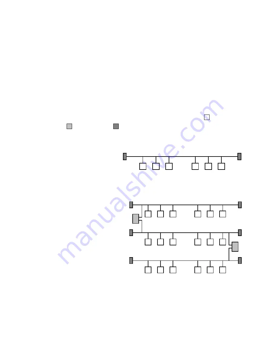
The bus structure is a line structure where each bus segment will
be blanked off with characteristic impedance on both ends.
Branches can be build up over a bi-directional signal amplifier, so
called repeater. Other than that branches are not permitted (no
tree topology). The max. stub to a user is not allowed to exceed
30 cm (12 inches).
The following figures show a few examples for a possible set-up
of bus topologies. The meaning of the symbols is: : bus user,
: repeater and : bus termination.
Figure 10.2 Simple
line
structure
Figure 10.3 Extended
line
structure
.....
.....
.....
.....
Summary of Contents for COMBILOG 1020
Page 1: ...COMBILOG 1020 Datalogger Hardware Manual Version 3 09...
Page 2: ...Hardware Manual COMBILOG 1020 2 Issue 03 11 2005 Technical data are subject to change...
Page 4: ...Hardware Manual COMBILOG 1020 4...
Page 6: ...Hardware Manual COMBILOG 1020 6...
Page 12: ...Hardware Manual COMBILOG 1020 12...
Page 86: ...Hardware Manual COMBILOG 1020 86 Bild 8 1 Example Master Slave System...
Page 169: ...Hardware Manual COMBILOG 1020 169...
Page 170: ...Hardware Manual COMBILOG 1020 170...


