3.2 Blower Switch
Turning “ON" the fan switch will cause the unit’s internal blower
to run continuously, whether the unit is dehumidifying or not. This
function is desirable if the unit is used for air circulation.
4. Maintenance
4.1 Air Filter
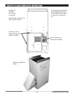
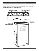
The Santa Fe Classic is equipped with 2 air filters. A foam pre-
filter followed by a standard MERV-11 65% efficient pleated fabric
filter. These should be checked every six months. Operating
the unit with dirty filters will reduce dehumidifier capacity and
efficiency and may cause the compressor to cycle off and on
unnecessarily on the defrost control.
If dirty, the foam pre-filter can be vacuumed or carefully hand
washed with warm water and mild detergent, then rinsed. The
pleated fabric filter can generally be vacuumed clean several
times before needing replacement. Replacement filters can be
ordered from the factory or purchased locally if available.
DO NOT
operate the unit without the filters or with a less effective filter.
The heat exchange coils inside the unit could become clogged and
require disassembly to clean.
5. Service
CAUTION!
Servicing the Santa Fe Classic with its high pressure
refrigerant system and high voltage circuitry presents a
health hazard which could result in death, serious bodily
injury, and/or property damage. Only qualified service people
should service this unit.
5.1 Warranty
A warranty certificate has been enclosed with this unit. Read
it before any repair is initiated. If a warranty repair is required,
call the factory first at 1-800-533-7533 for warranty claim
authorization and technical assistance.
5.2 Technical Description
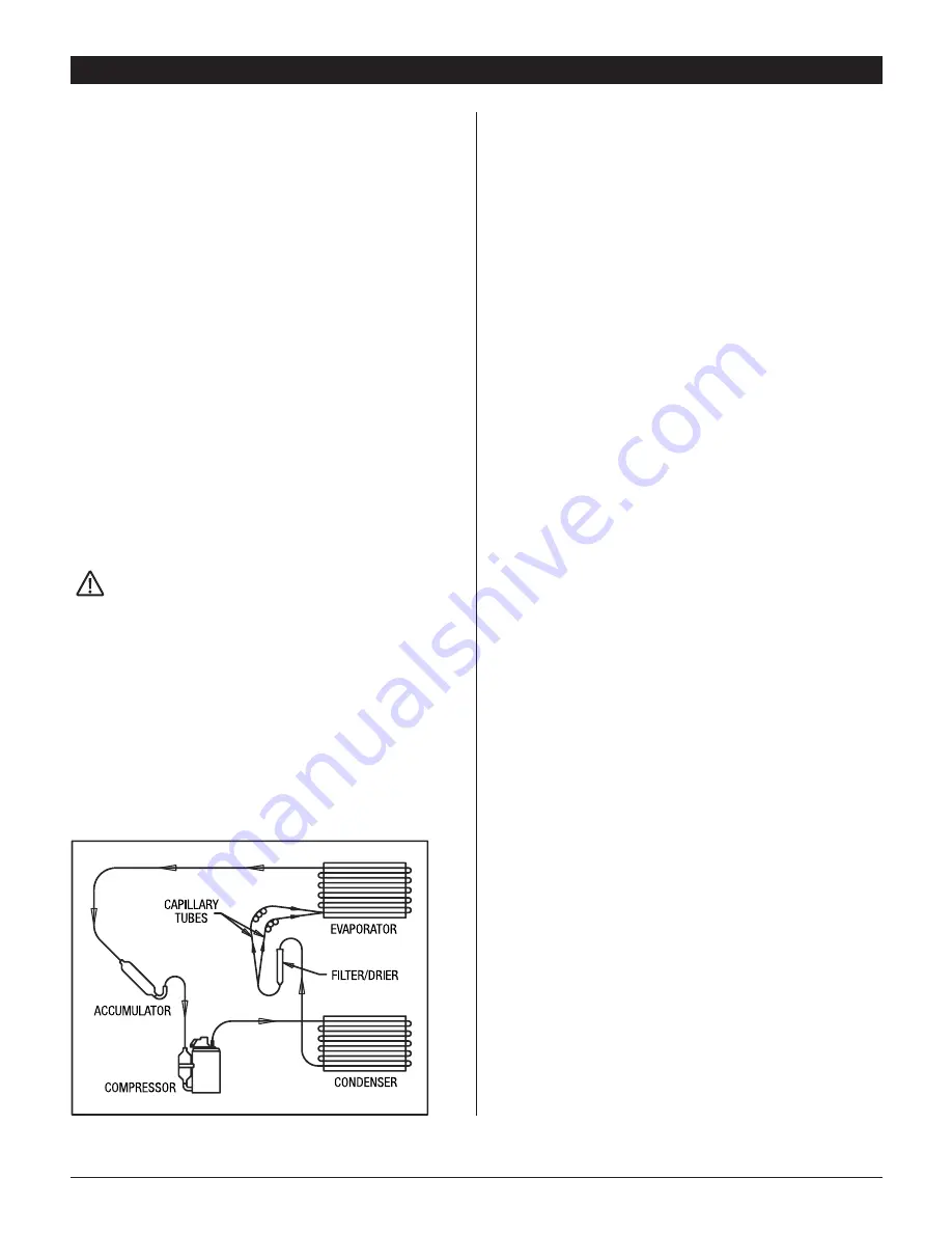
The Santa Fe Classic uses a refrigeration system similar to an air
conditioner’s to remove heat and moisture from incoming air, and
add heat to the air that is discharged (see figure 1).
Hot, high pressure refrigerant gas is routed from the compressor
to the condenser coil (see figure 1). The refrigerant is cooled
and condensed by giving up its heat to the air that is about to
be discharged from the unit. The refrigerant liquid then passes
through a filter/drier and capillary tubing which cause the refrigerant
pressure and temperature to drop. It next enters the evaporator coil
where it absorbs heat from the incoming air and evaporates
The evaporator operates in a flooded condition, which means that
all the evaporator tubes contain liquid refrigerant during normal
operation. A flooded evaporator should maintain constant pressure
and temperature across the entire coil, from inlet to outlet.
The mixture of gas and liquid refrigerant enter the accumulator
after leaving the evaporator coil. The accumulator prevents any
liquid refrigerant from reaching the compressor. The compressor
evacuates the cool refrigerant gas from the accumulator and
compresses it to a high pressure and temperature gas to repeat
the process.
5.3 Troubleshooting
No dehumidification. Neither blower nor compressor run with
fan switch “FAN AUTO”.
1. Unit unplugged or no power to outlet.
2. Humidity control set too high or defective
(Sec. 3.1 & 5.7).
3. Loose connection in internal wiring.
No dehumidification. Compressor does not run but blower
runs with fan switch “FAN AUTO” and humidity control turned
to ON (all the way clockwise).
1. Defective compressor or compressor run capacitor
(Sec. 5.6).
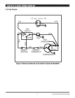
2. Loose connection in compressor circuit (see Fig. 2).
3. Defective compressor overload (Sec. 5.6A).
4. Defective compressor (Sec. 5.6).
5. Defrost thermostat open (Sec. 5.8).
Blower runs with fan switch “FAN AUTO”, but compressor cycles
ON & OFF.
1. Low ambient temperature and/or humidity causing
unit to cycle through defrost mode.
2. Defective compressor overload (Sec. 5.6A).
3. Defective compressor (Sec. 5.6).
4. Defrost thermostat defective (Sec. 5.8).
Blower does not run with fan switch in either position.
Compressor runs briefly but cycles ON & OFF.
1. Loose connection in blower circuit (see Fig. 2).
2. Obstruction prevents impeller rotation.
3. Defective blower.
4. Blower switch defective.
SANTA FE CLASSIC INSTALLER'S AND OWNER'S MANUAL
4
Santa Fe Classic Installer’s & Owner’s Manual

