background image

INSTALLATION  AND SAFETY GUIDELINES 


CLEARANCES 


The  unit  must  be kept clear  of all  combustibles. 


The  unit  must  be installed  with  the 4” legs  supplied  for  proper operation. 


Minimum  clearance  from  combustible  construction: 

Side               Back 

o


Open top 

12” 


12” 

o


Griddle 

6” 


12” 


Minimum  clearance  from  non-combustible: 

                                         Side                  Back 


Open top           0”                     0” 


Broiler   

 0”                     0” (For use in  noncombustible  locations  only) 


Griddle 

 0”                     6” 


LEVELING 
 

A carpenter’s  spirit  level  should  be placed  on the  cooking  surface  and the unit  leveled  side-to-side,  and front 
to back. If it  is  not level,  burner  combustion  may  be erratic  or the unit  may  not function  efficiently. 
 

AIR SUPPLY  AND VENTILATION 
 

The  area around  the  appliance  must  be kept clear  to avoid  any  obstructions  of  the flow  of  combustion  and 
ventilation  air  as well  as for ease of maintenance,  service,  and proper appliance  operation.  Keep clearance  for 
openings  into  the combustion  chamber  and adequate  air  supply.   Means must  be provided  for  any  commercial, 
heavy  duty-cooking  appliance  to exhaust  combustion  wastes  to the  outside  of the  building. 
 
Air  movement  should  be checked during  installation.   Strong  exhaust  fans  in  the hood or in  the  overall  air 
conditioning  system  can  produce a slight  draft  in  the room,  which  can interfere  with  pilot  or burner 
performance.   If  pilot  or burner  problems  persist,  make  up air  openings  or baffles  may  have  to be provided  in 
the  room. 
 
Filters  and drip  troughs  should  be part of any  industrial  hood, but  consult  local  codes before  constructing  and 
installing  any  hood.  The  duct system,  exhaust  hood, and filter  bank must  be cleaned  on a regular  basis  and 
kept free of  grease. 
 

ALTITUDE 
 

The  appliance  input  rating  (BTU/hr)  is  for elevations  up to 2000 feet.   For elevations  above 2000 feet,  the  rate 
should  be reduced 4% for each  1000 feet  above sea level.   The correct  orifices  are installed  at the  factory  if 
the  operating  altitude  is  known  at  the time  of sale. 


Summary of Contents for TC36-6

Page 1: ...MODEL TC36 6 shown COUNTER SERIES MODEL TC36RB shown MODEL TCHP36SU 6 shown MODEL TC36G shown OWNERS MANUAL AND INSTALLATION INSTRUCTIONS L LISTED U C US UL Made in U S A ...

Page 2: ...ANY OTHER APPLIANCE FOR YOUR SAFETY If you smell gas 1 Shut off gas to appliance 2 Extinguish any open flame 3 If odor continues immediately call your gas supplier Consult your local gas supplier for instructions to be followed in the event you smell gas Post these instructions in a prominent location WARNING IMPROPER INSTALLATION ADJUSTMENT ALTERATION SERVICE OR MAINTENANCE CAN CAUSE PROPERTY DAM...

Page 3: ...ulator will void the equipment warranty and result in a potentially hazardous condition The appliance and its individual shut off valve must be disconnected from the gas supply system during any pressure testing of that system in excess of PSI The appliance must be isolated from the gas supply system by closing its individual shut off valve during any pressure testing of the gas supply piping syst...

Page 4: ...arance for openings into the combustion chamber and adequate air supply Means must be provided for any commercial heavy duty cooking appliance to exhaust combustion wastes to the outside of the building Air movement should be checked during installation Strong exhaust fans in the hood or in the overall air conditioning system can produce a slight draft in the room which can interfere with pilot or...

Page 5: ...ly and blow them out with compressed air to clear any dirt particles threading chips or any other foreign matter before installing a service line Those particles will clog orifices when gas pressure is applied All connections must be sealed with a joint compound for LP gas and tested with a soapy water solution before lighting any pilots FLEXIBLE COUPLINGS CONNECTORS AND CASTERS If the unit is to ...

Page 6: ... valves and thermostats are in the off position LIGHTING THE PILOTS CAUTION When lighting the pilots and checking for leaks do not stand with your face close to the Combustion chamber OPEN TOP Remove top grates Make sure pilot adjust valve located on the manifold is open Light the pilot and adjust flame to approximately GRIDDLE Looking through slot in the valve panel locate pilot lighting holes in...

Page 7: ...ntire griddle surface 4 Turn all griddle burners to medium or thermostats to 350 degrees and wait until the shortening begins to smoke and then turn the burners off 5 Rub the now melted shortening into the griddle surface with a cloth covering the entire surface 6 Let the griddle cool and then repeat steps 3 4 5 7 When the griddle is cool after the second seasoning wipe it once again with a thin f...

Page 8: ...ed over about every week depending on the amount of cooking being done and the type of food being prepared GRIDDLE Scrape with a nylon griddle scraper to remove cooked on spills Use a fine grained stone only when absolutely necessary Wipe away any griddle stone dust and food particles with a cloth Wash with hot soapy water then rinse with vinegar and water solution Then rinse again with clean wate...

Page 9: ...l not ignite 1 Pilot blocked or dirty 2 Pilot adjusting screw closed 1 Clean pilot 2 Open adjust flame length Griddle too hot or not hot enough Thermostat out of calibration Check calibration HOW TO OBTAIN SERVICE For warranty service contact your local THERMA TEK authorized service agency Provide him or her with the Model Serial date of installation and a brief description of the problem If you n...

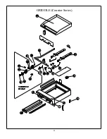
Page 10: ...9 HOT PLATE Counter Series ...

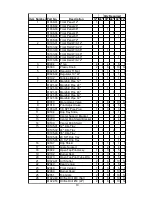
Page 11: ... Manifold Pipe 60 1 81021 06 Manifold Pipe 72 1 8 80030 Manual Gas Valve 2 4 6 8 10 12 9 81018 Pilot Adjust Valve 1 2 3 4 5 6 10 81003 01 1 8 NPT Pipe Plug 1 1 3 3 3 5 11 30194 Drip Tray Slide 1 1 1 12 30193 Center Support Bracket 2 4 4 13 30200 Center Drip Shield Bracket 4 4 4 14 30199 Center Drip Shield 1 1 1 15 30195 01 12 Drip Tray 1 30195 02 24 Drip Tray 1 2 30195 03 36 Drip Tray 1 2 30195 04...

Page 12: ...GRIDDLE Counter Series 11 ...

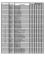
Page 13: ...lug 1 1 3 3 3 5 1 0 30221 Griddle Bucket 1 1 1 1 2 2 1 1 8001 5 01 BJ Thermostat Knob Griddle 1 1 2 2 3 3 1 2 8001 4 BJ Bezel 1 1 2 2 3 3 1 3 8001 7 01 BJWA Griddle Thermostat 1 1 2 2 3 3 1 4 8001 9 TEE Thermostat 1 1 2 2 3 3 1 5 81 01 5 90 Elbow 3 8 CC x 1 4 NPT 1 1 1 1 6 81 027 TEE 3 8 CC 1 4 NPT 1 2 3 3 1 7 9001 3 3 8 x 8 Flexible Gas Tubing 1 2 3 4 5 6 1 8 81 01 4 Elbow 3 8 TOD 3 8 27 UNS 1 2 ...

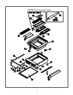
Page 14: ...BROILER Counter Series 13 ...

Page 15: ...ray 1 2 1 30195 03 36 Drip Tray 1 1 2 30195 04 29 5 8 Drip Tray 1 30195 05 23 Drip Tray 1 11 81026 Pilot Valve TEE 3 16 1 12 81014 Elbow 3 8 TOD 3 8 27 UNS 1 2 3 4 5 6 13 81016 01 Orifice Elbow 3 8 27 x 3 8 CC 1 2 3 4 5 6 14 90013 3 8 x 8 Flexible Gas Tubing 1 1 2 2 3 3 15 81022 39 Orifice Drill 39 Nat 1 2 3 4 5 6 81022 52 Orifice Drill 52 LP 1 2 3 4 5 6 16 90038 Pilot Tip Assy 3 16 x 12 5 Lg 1 2 ...

Page 16: ...goodworkingcondition AuthorizedService Agencymay require a credit cardbefore entering premises for non warrantedissues 8 This states the exclusive remedyagainst Therma Tekrelatingtothe product s whether in contract orin tort orunder anyother legal theory andwhether Arisingout of warranties representations instructions installations or defects from any cause 9 This warrantyandthe liabilities set fo...

Reviews: