background image

EX-TRACK

®

Operator Manual, Revision T-1

118

Notes:

Summary of Contents for EX-TRACK

Page 1: ...PORTABLE CNC CUTTING SYSTEM Operator Manual EX 0 902 001 N 22063 Revision Date December 01 2019 Revision Number 01 3 Language English...

Page 2: ...andling of the system refer to Thermacut s terms and conditions of sale for specific responsibilities and limitations on liability Information in this document is subject to change without notice The...

Page 3: ...isk of fire 15 1 2 6 Risk of burn injury 15 1 2 7 Safety in the workplace 16 2 LOCATION OF WARNING AND SAFETY LABELS 18 3 SPECIFICATION 22 3 1 System overview 23 3 1 1 Main features 23 3 1 2 Range of...

Page 4: ...ration 39 6 2 Plasma arc cutting prior to operation 40 7 MAINTENANCE 41 7 1 Cleaning the system 42 7 2 System lubrication 42 7 3 Drive motor adjustment 42 7 4 Oxy fuel nozzle maintenance 42 8 CIRCUIT...

Page 5: ...2 7 Return F7 57 9 5 Automatic program mode 57 9 5 1 Cutting speed 58 9 5 2 Process start point 58 9 5 3 Active key functions when running a program 58 9 5 4 Active key functions in pause mode 59 9 5...

Page 6: ...0 1 CNC program symbols G codes 76 9 10 2 File types 77 9 10 3 File names 77 9 10 4 Units of measurement 77 9 10 5 Programming 77 9 10 6 System axes 77 9 10 7 G codes 78 9 10 8 G92 program zero point...

Page 7: ...3 10 5 Changing System name text 95 10 6 Hardware service instructions 95 10 6 1 Replacing main fuse 95 11 Warranty terms and conditions 97 S Mark 98 CE Mark 98 C Tick Mark 98 12 Certification and com...

Page 8: ...Shape 29 110 Shape 30 110 Shape 31 111 Shape 32 111 Shape 33 111 Shape 34 112 Shape 35 112 Shape 36 112 Shape 37 113 Shape 38 113 Shape 39 113 Shape 40 114 Shape 41 114 Shape 42 114 Shape 43 115 Shap...

Page 9: ...1 1 3 Safety precautions prior to handling and operation 13 1 2 Plasma oxy fuel gas cutting safety awareness 14 1 2 1 Prevention of fire and explosion 14 1 2 2 Safe use of gas pressure regulators 14...

Page 10: ...he system The system safety label categories are as follows WARNING CAUTION NOTICE SIGNS This symbol is used as a warning message or a warning label It is positioned at places that could cause injury...

Page 11: ...ators must ground the equipment using the safety grounding terminal on power plug Pull out the power plug from the outlet Operators must unplug the power plug from the outlet when a failure occurs or...

Page 12: ...tened using a suitable wrench perform a leak test and retighten as required 3 When fixing a nozzle to the oxy fuel torch tighten the nut with two wrenches In addition avoid damaging the seat of the no...

Page 13: ...to do so can result in injury 9 To reduce the risk of an accident prohibit the touching of moving parts while the system is running 10 DO NOT use the EX TRACK for welding purposes the circuit boards w...

Page 14: ...g a sudden violent shock that can cause damage 3 Check the pressure gauge dial to ensure the pressure indicator is not sticking listen for gas leaks Do not use damaged or leaking pressure regulators 4...

Page 15: ...e liquids gases vapors and other combustible flammable materials ensure that suitable fire extinguishers for use on Gas Electrical Hot metal fires are suitably located locate fire buckets with sand wa...

Page 16: ...ng device allow adequate time for the system to cool down after cutting 1 2 7 Safety in the workplace 1 Use of the cutting processes will produce but not be limited to the following Sparks molten meta...

Page 17: ...ts If during the cutting process there is the odor from a gas leak immediately press the E Stop button to isolate the electrical power supply turn off the gas supply at the torch and then at the point...

Page 18: ...n burn eyes and skin Noise can damage hearing Flying sparks arc spray can cause injury fire or explosion Caution Read operator s manual Cutting can cause fire or explosion Electric shock can kill Plas...

Page 19: ...produce intense visible and invisible rays that can burn eyes and skin Use protective clothing made from durable flame resistant material appropriate footwear and hand protection Use face protection...

Page 20: ...liquids and materials remove prior to cutting as they present a fire risk EXPLOSION PREVENTION Do not cut in areas containing explosives flammable gases or vapors Do not place the system on over or n...

Page 21: ...AN BE HAZARDOUS Work in a confined space only if it is well ventilated or while wearing an air supplied respirator The smoke and gases from the cutting gouging process can displace air and lower the o...

Page 22: ...Revision T 1 22 SECTION 3 SPECIFICATION 3 1 System overview 23 3 1 1 Main features 23 3 1 2 Range of application 23 3 2 System parts description 23 3 3 Technical parameters 24 3 4 Torch height control...

Page 23: ...5 7 high resolution LCD display It can be manually programmed it is able generate its own programs from a library of common shapes alternatively programs can be loaded through the USB port from off l...

Page 24: ...ing speed mm min 50 3000 Maximum position speed mm min 3000 Overall dimensions l h w mm 3500 370 2200 Weight kg 134 3 4 Torch height controller Oxy fuel Torch comprises of torch body two way valve gas...

Page 25: ...t and vertical positioning can be adjusted manually so as to ensure that cut is square For edge beveling rotate the torch along the longitudinal or transverse direction to perform an angled cut 3 5 Ga...

Page 26: ...1 Packing list 27 4 2 System assembly 28 4 2 1 Parts check 28 4 2 2 Fitting the main unit on to the longitudinal guide rail 28 4 2 3 Fitting the transverse guide rail 29 4 2 4 Fitting the torch height...

Page 27: ...y Note Assembled parts 1 Main unit CNC unit 1 2 Transverse rails 1 Aluminum profile 3 Longitudinal rails 1 4 Torch assembly 1 5 Power lead and Plasma Interface cable 1 length 3m Technical literature 1...

Page 28: ...nd then carefully feed the main unit on to the rail guide it is recommended that this is done with two people Gently feed the main unit on to the guide rail until the main unit drive assembly is fully...

Page 29: ...main unit case then place the transverse rail in the horizontal plane as shown in Figure 3 gently feed the rail in through the main unit until the rack meshes with the drive gear in the main unit 4 2...

Page 30: ...suitable leak test product ensure that there are no leaks prior to use The Oxy fuel hoses fitted to this system are standard 8mm internal diameter hoses Where possible use the minimum length of hose...

Page 31: ...a grounding wire earth it is to be plugged in to a mains network socket that is equipped with a mating ground earth terminal connection and supply are to be in accordance with local electrical codes...

Page 32: ...placement 33 5 1 3 Oxy fuel nozzle choice 33 5 1 4 Regulated gas supply 33 5 1 5 Oxy fuel cut charts 33 5 1 6 Pre ignition check 34 5 2 Ignition and flame adjustment oxy propane cutting 34 5 3 Cut qua...

Page 33: ...ss of the steel plate Select a larger size nozzle if the steel is heavily rusted or for bevel cutting at angles greater than 20 5 1 4 Regulated gas supply The EX TRACK CNC Cutting System requires a re...

Page 34: ...n preheating valve on the torch a 1 2 turn and ignite the gas flow at the torch tip 3 Gradually unscrew the fuel gas valve and oxygen preheating valve on the torch until the required Neutral flame is...

Page 35: ...this should be performed only by experienced operators Using a drilled hole is an alternative method for piercing thick material this enables an edge start to the cutting process Frequently check the...

Page 36: ...n certain countries it is mandatory for flashback arrestors to be fitted to the torch as well as the regulators It is the operator s responsibility to ensure compliance with local national and interna...

Page 37: ...EX TRACK Operator Manual Revision T 1 37 Turning the torch off 1 Close the oxygen preheating valve 2 Close the fuel gas valve 3 Close the oxygen cutting valve...

Page 38: ...EX TRACK Operator Manual Revision T 1 38 SECTION 6 SYSTEM OPERATION 6 1 Oxy fuel cutting prior to operation 39 6 2 Plasma arc cutting prior to operation 40...

Page 39: ...ashback occurs press the E Stop button then immediately turn off the fuel gas at the torch then close off the heating and cutting oxygen supply Wear gloves when turning off the gas supply at the torch...

Page 40: ...asma arc ignition the work area should be vacated by non essential personnel Operators should use the most appropriate piercing method to reduce flying sparks and damage to the torch consumables and s...

Page 41: ...EX TRACK Operator Manual Revision T 1 41 SECTION 7 MAINTENANCE 7 1 Cleaning the system 42 7 2 System lubrication 42 7 3 Drive motor adjustment 42 7 4 Oxy fuel nozzle maintenance 42...

Page 42: ...ed on the rack but sparingly as excessive lubricant will attract a contaminant buildup Keep the system main unit clean use a soft cloth to wipe down the CNC operator panel ensure that the USB port cov...

Page 43: ...2 13 I12 8 15 24V GND I8 I9 I10 I11 Wireless reception module 24V 0V AC220V AC220V 2 Plasma Start 1 Plasma Start 5 ARC 6 ARC 1 50 3 4 Plasma torch switch 6 5 3 4 201 203 M 3 4 6 7 2 5 1 Z0 Preheat sol...

Page 44: ...connecting the system interface lead to the plasma arc power supply Signal Start Arc Trans Voltage Divider Type Output Input Input Note Normally open Dry contact Normally open Dry contact from plasma...

Page 45: ...9 4 2 Auto processing menu MAIN MENU F1 AUTO 53 9 4 2 1 Pierce point F1 SECTION 53 9 4 2 2 Manual mode F2 MANUAL 53 9 4 2 3 Break point F3 BRK 53 9 4 2 4 Graphics display F4 54 9 4 2 5 Kerf F5 54 9 4...

Page 46: ...e F3 66 9 7 1 4 Delete files F4 66 9 7 1 5 Delete line F5 66 9 7 1 6 USB F6 66 9 7 1 7 View F7 66 9 8 Setup F4 PARAMER 66 9 8 1 Process definition speed 66 9 8 2 Speed parameters F1 67 9 8 3 System pa...

Page 47: ...lation motion in a straight line 79 9 10 15 G02 G03 circular interpolation motion along a circular arc 79 9 10 16 G04 pause dwell 79 9 10 17 G40 kerf off compensation factor 79 9 10 18 G41 kerf left 8...

Page 48: ...y shape check and workpiece alignment fit up 7 Quick program access to any line or pierce start point in a single or nested program 8 Suited for use in a wide variety of applications in the metalworki...

Page 49: ...ed Axes X Y and Z Vertical with Height Controller Top speed 3000mm min Pulse equivalent Flexible adjustment Operating temperature 0 to 40 C storage temperature 30 to 60 C Storage space 4Gb super progr...

Page 50: ...sition the cutting torch F3 EDITOR Edit modify USB input USB output processing program F4 PARAMER System parameter settings F5 DIAGNOSE Check machine input and output information F6 LIBRARY Access sta...

Page 51: ...own in the display can be in Metric or Inch increments changes can be made in Setting Parameters Control Metric Inch option 9 4 1 2 Prog pierce kerf As displayed at the top of the screen PROG shows th...

Page 52: ...d process for lowering torch at the start of the oxy fuel cut PIERCEUP HIGH M72 timed process for raising the torch at the start of the piercing PIERCEDN HIGH M73 timed process for lowering the torch...

Page 53: ...ems memory 9 4 2 1 Pierce point F1 SECTION The Pierce Point function permits the operator to pick a pierce point from where the cutting process can be re started Using function F5 the operator can inp...

Page 54: ...ted cut area Press 1 key to magnify the profile part Image press up to 3x for a maximum 8x magnification Press 2 Returns image to original format 9 4 2 5 Kerf F5 Use this function to enter a kerf comp...

Page 55: ...te press STOP reposition the torch to within the perimeter of the plate press START A screen prompt in the Mode Status section requires an input for REPOSITION YES NO Press ENTER to confirm reposition...

Page 56: ...he size input value will be logged for re use the value can also be reset to zero in this process 9 4 2 6 5 Nest F6 When using the Nest function a profile part or multiple parts can be nested using th...

Page 57: ...uto Mode MORE menu 9 4 2 7 Return F7 The RETURN function enables the system to quickly return to the ZERO point in a program or the system ZERO point Press key F7 to initiate the RETURN The operator c...

Page 58: ...hange is slow during the cutting process giving greater control over the effect of speed change to the profile part Making a significant speed change to the cutting process will require the process to...

Page 59: ...ocess will require a manual re start Jog Keys pausing the cutting process allows the torch to be positioned where consumable parts can be checked changed correcting the cut path or realign the plate T...

Page 60: ...al Automatic mode select then ENTER F4 STEP the operator can choose to re start the cutting sequence at any position in the program In the STEP Mode keys F6 F7 are used for scrolling through the progr...

Page 61: ...original cutting sequence is followed from this point STEP OVERRIDE this function will override the STEP process reverting the process back to the cut sequence Pressing START or ENTER initiates the f...

Page 62: ...the cutting sequence at that point the system will cut to the pierce point and resume cutting along the cut path NO PIERCE this option is used when piercing is not required Note With oxy fuel cutting...

Page 63: ...anual setting is used to reposition the torch or maneuver the system for material realignment Switching from the Manual Mode to the Auto Mode in the 1st level of the menu using the F1 function key let...

Page 64: ...wn and then ENTER for the chosen option Zero all coordinates This resets ALL X and Y system and program coordinates back to zero Setup coordinates With this function the operator can input new program...

Page 65: ...using the keypad manually enter the program code 9 7 1 2 Load F2 Use this function to insert a program into the live program memory the program is shown in the program editor and can be accessed in t...

Page 66: ...d store in the systems memory The USB memory stick can be used to upload programs for storage or transfer in the OUTPUT mode press F2 to store the data 9 7 1 7 View F7 Lets the operator see an on scre...

Page 67: ...is the adjusted ramp down up speed at corners change of direction MAX JOG SPEED this is the maximum speed the system will travel in the Manual Step Mode and repositioning when in a program Program com...

Page 68: ...re adjusted from the factory NUMERATOR numerical analysis used for positioning accuracy MA ORIGIN start point for the System Coordinates REFERENCE POINT start point for the Program Coordinates DRILL O...

Page 69: ...g oxygen TORCHUP TIME M70 It is a time of the torch movement up in sec from the cutting height to height for manual ignition of the flame TORCHDN TIME M71 Is is a time of the torch movement down in se...

Page 70: ...ressing the F4 key FIND IHS HEIGHT 0 1 switch on initial height sensing for plasma torch IHS LOGIC set this to 0 for EX TRACK CNC SYSTEM working with the EX TRAFIRE PLASMA SYSTEM IHS TIMER turn on aut...

Page 71: ...controller will be shut off SPEED FOR OFF AHCS the speed to shut off the height controller The cutting speed low than this set parameter the height controller will be shut off This function main for...

Page 72: ...k for kerf faults No 0 Yes 1 INITIAL CLEAR DOOR program coordinates are automatically reset to zero when a program starts SELECT CYLINDER UP DOWN function not used with EX TRACK CNC SYSTEM SELECT AUTO...

Page 73: ...r Plasma power source arc transfere signal THC ENABLE enable automatic torch height control 0 off 1 on THC AUTO ENABLE automatic start and stop during cutting 0 off 1 on THC NUMBER this number no func...

Page 74: ...peed for manual lift up down manual speed AUTO SPEED the torch up down speed for automatic lift POSITION SPEED the torch up down speed for the initial position 9 9 3 Save F7 This key save all adjusted...

Page 75: ...displayed in the edit screen Press the F7 VIEW key for showing the shape Press the F3 key for the SAVE function input a program filename and save it to the program storage memory The saved file can b...

Page 76: ...red fit gives better results After the choosing the shape in graphic library and adjusting the dimensions press the ESC key for access to main menu Press F1 AUTO in main menu press F4 PREVIEW press ES...

Page 77: ...File names can be created within the system for easy recall the file name is compiled using a maximum of 8 Name characters a period decimal point and 3 file type extension characters The recognized f...

Page 78: ...is pressed it clears the G92 value from the system memory Format G92 Xn Yn 9 10 9 G90 absolute commands The G90 code means that you are working from an absolute datum zero point every position or move...

Page 79: ...9 10 15 G02 G03 circular interpolation motion along a circular arc Circular interpolation requires the system to precisely coordinate two axes G02 establishes a mode for clockwise circular arcs G03 e...

Page 80: ...sed to return the torch to the systems reference position also called zero position The torch travels in the X Y axes at the G00 maximum speed Format G28 Return to reference point 9 10 21 G22 G80 cycl...

Page 81: ...The M08 code is used to shut down the oxy fuel and plasma cutting processes the sequence for oxy fuel cutting is pauses system travel shuts the cutting oxygen valve starts the bleed down timer pause i...

Page 82: ...g the system 10 1 FAQ s Operating the system 83 10 2 Basic trouble shooting 85 10 3 Software service instructions Boot menu 92 10 4 Backup and restore parameters 93 10 5 Changing System name text 95 1...

Page 83: ...the pierce point You may then re start the cutting process and press the START key to begin cutting again Q If the power is lost during cutting or some other interruption causes the program to be aban...

Page 84: ...ill cause the CNC to repeatedly attempt to read a file which cannot be understood by the CNC so it appears to be locked up It is suggested that the USB stick be freshly re formatted and only the neces...

Page 85: ...Check plugs and cables at both ends of Transverse rail Check plug on Connector Panel on rear of Main Unit Inspect cable for damage Lift Motor or Micro Switch Failed Check for 24 VDC at motor cable plu...

Page 86: ...nnected Plate may not have sufficient electrical contact with table Fix or tighten ground connection Ground directly to the plate if necessary Check connection of red torch wire at the shield cap Conn...

Page 87: ...shown while running a part Check parameter settings Parameter may be set incorrectly or parameters may be corrupted Make sure Control Parameter for No Graphics is set to 0 OFF System suddenly stops in...

Page 88: ...e making any modification Check motor to make sure it is not frozen or jammed Motor may be damaged Replace motor if damaged CNC is slow to respond Check the power supply Output voltage may be below th...

Page 89: ...Save the parameters and test the system performance No input output Check the cables connected to the rear of the Central Unit Loose connection or broken wires Secure the connection or replace cables...

Page 90: ...e USB stick connector using non conductive tool and vacuum Keep cover closed over USB port Inspect condition of USB port and USB stick connector Damaged or broken pins contacts can disrupt operation D...

Page 91: ...cable Electrical noise loose ground connection Make sure ground connection is tight and is making good electrical contact Make sure all cables are connected properly and are in good condition Outputs...

Page 92: ...Menu has three options The three options are 1 Parameter Load factory settings This function erase all settings and drawings from the CNC unit 2 File format By this function you can erase all drawings...

Page 93: ...hen this mode is selected the F7 key changes to show FACTORY in each of the Parameter Groups All changes that are made will be saved as Factory Settings when the F7 key is pressed 2 Save parameters to...

Page 94: ...te operation 4 If the update is successful the system will display PLEASE REBOOT and sound two beep If the update fails the system will display UPDATE FAILED and sound continuous beeps 5 Power the sys...

Page 95: ...f necessary to return to the Main menu Press these keys one after the other G G 8 A prompt will appear asking you to press ENTER to confirm changing the Name Text or ESC to abort changing the Name Tex...

Page 96: ...EX TRACK Operator Manual Revision T 1 96 Number Description 1 Power switch 2 Main power fuse 3 Power connector 1 2 3...

Page 97: ...nsferable See the exact terms and conditions of the warranty on the Bill of Sale or Invoice The warranty will not be valid if 1 After purchasing damage is caused by improper transportation or storage...

Page 98: ...e for use in environments with danger of electrocution The hand torches must have shielded consumable parts fitted to maintain mark compliance CE Mark This marking signifies the manufacturer s declara...

Page 99: ...3 105 Shape 14 105 Shape 15 105 Shape 16 106 Shape 17 106 Shape 18 106 Shape 19 107 Shape 20 107 Shape 21 107 Shape 22 108 Shape 23 108 Shape 24 108 Shape 25 109 Shape 26 109 Shape 27 109 Shape 28 110...

Page 100: ...EX TRACK Operator Manual Revision T 1 100 Shape 42 114 Shape 43 115 Shape 44 115 Shape 45 115 Shape 46 116 Shape 47 116 Shape 48 116 Shape 49 117 Shape 50 117 Notes 118 Revision history 119...

Page 101: ...EX TRACK Operator Manual Revision T 1 101 Shape 1 Shape 2 Shape 3...

Page 102: ...EX TRACK Operator Manual Revision T 1 102 Shape 4 Shape 5 Shape 6...

Page 103: ...EX TRACK Operator Manual Revision T 1 103 Shape 7 Shape 8 Shape 9...

Page 104: ...EX TRACK Operator Manual Revision T 1 104 Shape 10 Shape 11 Shape 12...

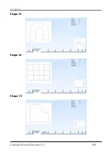
Page 105: ...EX TRACK Operator Manual Revision T 1 105 Shape 13 Shape 14 Shape 15...

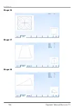
Page 106: ...EX TRACK Operator Manual Revision T 1 106 Shape 16 Shape 17 Shape 18...

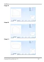
Page 107: ...EX TRACK Operator Manual Revision T 1 107 Shape 19 Shape 20 Shape 21...

Page 108: ...EX TRACK Operator Manual Revision T 1 108 Shape 22 Shape 23 Shape 24...

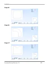
Page 109: ...EX TRACK Operator Manual Revision T 1 109 Shape 25 Shape 26 Shape 27...

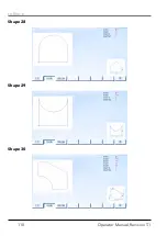
Page 110: ...EX TRACK Operator Manual Revision T 1 110 Shape 28 Shape 29 Shape 30...

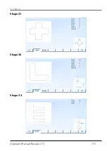
Page 111: ...EX TRACK Operator Manual Revision T 1 111 Shape 31 Shape 32 Shape 33...

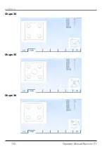
Page 112: ...EX TRACK Operator Manual Revision T 1 112 Shape 34 Shape 35 Shape 36...

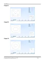
Page 113: ...EX TRACK Operator Manual Revision T 1 113 Shape 37 Shape 38 Shape 39...

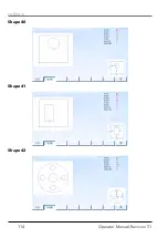
Page 114: ...EX TRACK Operator Manual Revision T 1 114 Shape 40 Shape 41 Shape 42...

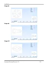
Page 115: ...EX TRACK Operator Manual Revision T 1 115 Shape 43 Shape 44 Shape 45...

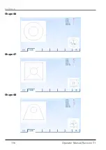
Page 116: ...EX TRACK Operator Manual Revision T 1 116 Shape 46 Shape 47 Shape 48...

Page 117: ...EX TRACK Operator Manual Revision T 1 117 Shape 49 Shape 50...

Page 118: ...EX TRACK Operator Manual Revision T 1 118 Notes...

Page 119: ...vision history 1 Revision Nr 01 1 06 2019 Official release 2 Revision Nr 01 2 10 2019 Page 24 changed texts in table a Supply voltage from AC220V 50HZ to AC110V 230V 50HZ b Cutting speed mm min from 5...

Page 120: ...Kft Pet fi S ndor utca 37 atd 2500 Esztergom HUNGARY Tel 36 33 502 090 1 Fax 36 33 400 004 E mail info thermacut hu www thermacut hu THERMACUT SLOVAKIA s r o M R tef nika 14 942 01 urany SLOVAKIA Tel...

Page 121: ...574 Ma atice 686 01 Uhersk Hradi t Czech Republic www thermacut cz sales thermacut cz THERMACUT FHT EX and EX TRAFIRE are registered trademarks of THERMACUT k s and may be registered in Czech Republic...

Reviews: