EX-TRACK
®
Operator Manual, Revision T-1
34
Nozzle type
Work-piece
thickness
(mm)
Pressure
(bar)
Consumption
(Nl/h)
Cutting
speed
(mm/min)
Oxygen
Fuel gas
Cutting O
2
Preheat O
2
Fuel gas
1.
5 - 10
2.0
0.2
1200
1180
310
660 - 550
2.
10 - 15
2.5
0.2
2100
1180
310
550 - 490
3.
15 - 30
3.0
0.25
3400
1370
360
490 - 400
4.
30 - 40
3.0
0.25
4300
1370
360
400 - 350
5.
40 - 50
3.5
0.3
6500
1860
490
350 - 320
6.
50 - 100
4.0
0.3
11000
1860
490
320 - 200
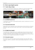
5.1.6. Pre-ignition check
Prior to the torch being ignited, it is advisable to make a dry run on the workpiece, ensuring that the
cut path matches the profile shape required.
5.2. Ignition and flame adjustment - oxy propane cutting
The following information relates solely to Oxy Propane cutting, for alternative gases such as
Acetylene, seek advice from your gas supplier. Use the cut chart data as a guide, adjust the gas flow
pressure at the regulator, after ignition further adjustment to the flame may be required.
1. Unscrew the fuel gas valve on the torch, a 1/4 turn.
2. Unscrew the oxygen preheating valve on the torch, a 1/2 turn and ignite the gas flow at the
torch tip.
3. Gradually unscrew the fuel gas valve and oxygen preheating valve on the torch, until the
required Neutral flame is achieved. See images of the carburizing, oxidizing and neutral flame
profiles.
4. Approximate distance between the cutting nozzle face and the workpiece:
Propane gas 8 - 10mm
5. A neutral flame, correct nozzle size, travel speed and torch height are required to achieve
the desired profile cut finish. The cleaning of profile parts is easy when all parameters are set
correctly.
6. Ensure the nozzle size used is suited to the material thickness, a nozzle that is too big in
size for thin material will cause the material to distort and have a poor cut quality, likewise,
a nozzle that is too small for thick material will travel too slow, cause edge damage and
possible incomplete severance of the part. Flashbacks can occur from cutting with incorrect
settings, ensure “Flashback Arrestors” are fitted, used correctly and maintained.
7. To maintain a constant cut quality, ensure settings are adjusted as required, use the supplied
nozzle cleaning kit to keep the nozzle clean and free from dross and spatter.
Summary of Contents for EX-TRACK
Page 101: ...EX TRACK Operator Manual Revision T 1 101 Shape 1 Shape 2 Shape 3...
Page 102: ...EX TRACK Operator Manual Revision T 1 102 Shape 4 Shape 5 Shape 6...
Page 103: ...EX TRACK Operator Manual Revision T 1 103 Shape 7 Shape 8 Shape 9...
Page 104: ...EX TRACK Operator Manual Revision T 1 104 Shape 10 Shape 11 Shape 12...
Page 105: ...EX TRACK Operator Manual Revision T 1 105 Shape 13 Shape 14 Shape 15...
Page 106: ...EX TRACK Operator Manual Revision T 1 106 Shape 16 Shape 17 Shape 18...
Page 107: ...EX TRACK Operator Manual Revision T 1 107 Shape 19 Shape 20 Shape 21...
Page 108: ...EX TRACK Operator Manual Revision T 1 108 Shape 22 Shape 23 Shape 24...
Page 109: ...EX TRACK Operator Manual Revision T 1 109 Shape 25 Shape 26 Shape 27...
Page 110: ...EX TRACK Operator Manual Revision T 1 110 Shape 28 Shape 29 Shape 30...
Page 111: ...EX TRACK Operator Manual Revision T 1 111 Shape 31 Shape 32 Shape 33...
Page 112: ...EX TRACK Operator Manual Revision T 1 112 Shape 34 Shape 35 Shape 36...
Page 113: ...EX TRACK Operator Manual Revision T 1 113 Shape 37 Shape 38 Shape 39...
Page 114: ...EX TRACK Operator Manual Revision T 1 114 Shape 40 Shape 41 Shape 42...
Page 115: ...EX TRACK Operator Manual Revision T 1 115 Shape 43 Shape 44 Shape 45...
Page 116: ...EX TRACK Operator Manual Revision T 1 116 Shape 46 Shape 47 Shape 48...
Page 117: ...EX TRACK Operator Manual Revision T 1 117 Shape 49 Shape 50...
Page 118: ...EX TRACK Operator Manual Revision T 1 118 Notes...

