

Page 7
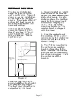
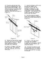
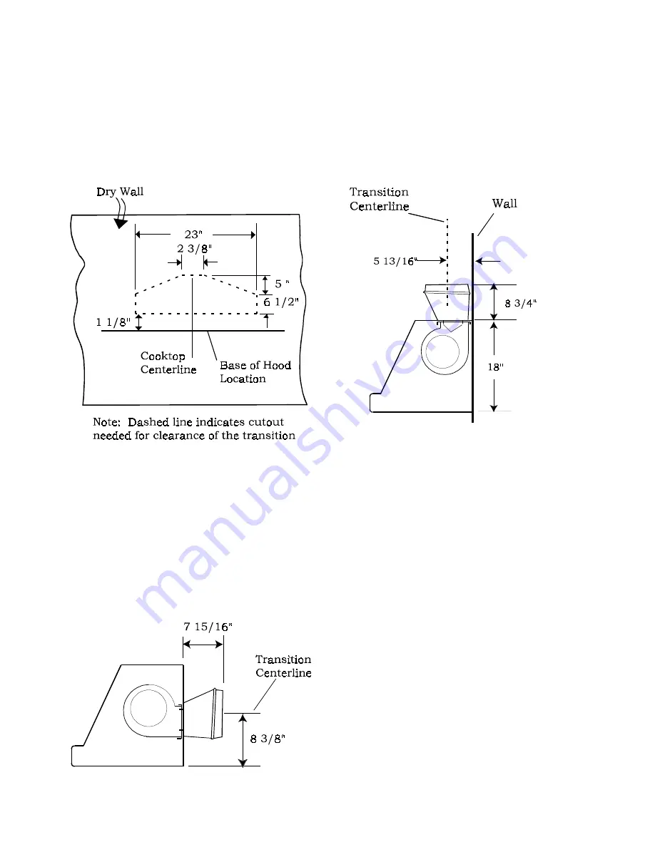
11. Discharge Direction: Hori-
zontal discharge requires a wall
cutout, as shown in Figure 5, to
provide clearance for the transi-
tion. The location of the cutout is
determined by the hood installa-
tion height.
Figure 5
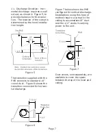
The transition supplied with the
PHE connects to standard 10”
round duct. Figure 6 shows the
transition connected for horizon-
tal discharge.
Figure 7 below shows the PHE
configured for vertical discharge.
Installations using this type of
method require a cutout in the
ceiling to accomodate 10” duct
and the 1/2” conduit carrying
power to the unit.
Figure 7
Duct covers, sold separately, are
available to cover the space
between the top of the hood and
ceiling.
Figure 6


