English 15
Preparing the Ceiling Cutout and Housing
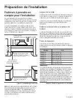
The unit must be mounted to the surrounding housing. See
“Installation Preparation” on page 5
for suggestions on
determining hood height.
When calculating the load for the housing support system, be sure to include the weight of the ventilation unit. See
Table 2
on page 5
for unit weight by model.
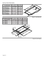
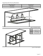
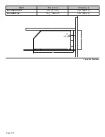
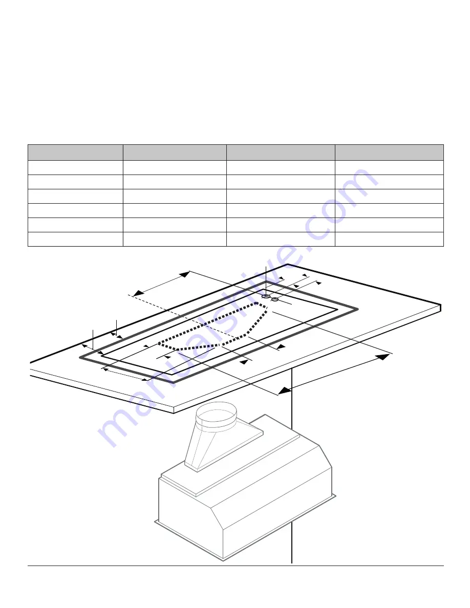
Build housing in accordance with the dimensions noted in
Figure 26
thru
Figure 28
.
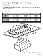
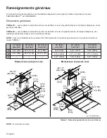
Transition and Conduit Cutout Dimensions
Model
A
B
C
36'' without Liner
14
3
/
16
'' (360 mm)
1
ǩ
'' (29 mm)
1
Ǭ
'' (47 mm)
48'' without Liner
19
13
/
16
'' (503 mm)
1
ǩ
'' (29 mm)
1
Ǭ
'' (47 mm)
54'' without Liner
22
13
/
16
'' (579 mm)
1
ǩ
'' (29 mm)
1
Ǭ
'' (47 mm)
36'' with LINER236
14
3
/
16
'' (360 mm)
3
3
/
16
'' (81 mm)
1
ǩ
'' (29 mm)
48'' with LINER248
19
13
/
16
'' (503 mm)
3
3
/
16
'' (81 mm)
1
ǩ
'' (29 mm)
54'' with LINER254
22
13
/
16
'' (579 mm)
3
3
/
16
'' (81 mm)
1
ǩ
'' (29 mm)
Figure 23: Transition and Conduit Cutout Dimensions
2
3/8
"
(86)
2
3/8
"
(86)
2
3/8
"
(86)
Back of Hood
Back of Trim or Liner
Back of Trim or Liner
Back of Trim or Liner
CLCLCL
C
B
B
10¼"
(260)
10¼"
(260)
10¼"
(260)
3
3
3/3/
3/
16
16
16
"
"
(81 )
(81 )
(81 )
7
7
7/
7/
8
8
"
"
(200)
(200)
(200)
Dia. clearance holes for 1"
(25.4) conduit to junction box
Dia. clearance holes for 1"
(25.4) conduit to junction box
Dia. clearance holes for 1"
(25.4) conduit to junction box
23" (584)
23" (584)
23" (584)
A
A
1
1
7/
7/
"
"
(48)
(48)
(48)
8
8


