background image

English 7

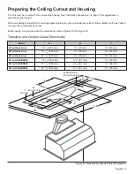
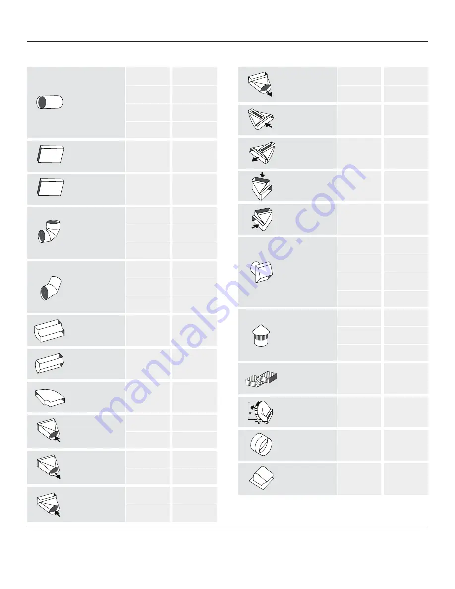
Equivalent Duct Lengths for Commonly Used Transitions

Smooth  
Straight

6

1.2

7

0.95

8

0.7

10

0.6

3¼" x 10" 
Straight

N/A

1

 3¼"  x 14" 
Straight

N/A

0.7

90° Elbow   
Round

6

12

7

8

8

6

 45° Elbow   
Round

6

5

7

4

8

3

"

 x 10" 


90° Elbow   
Round

N/A

5

3¼” x 10" 


45° Elbow   
Round

N/A

15

"

 x 10" 


Flat Elbow

N/A

20

Round to  

"

 x 10"

6

1

7

1

"

 x 10"


to Round

6

5

7

3

Round to   

"

 x 10" 


90° Elbow

6

10

7

8

"

 x 10" 


to Round   
90° Elbow

6

10

7

5

"

 x 10" 


Center Reverse 
Elbow Left

N/A

15

"

 x 10" 


Center Reverse 
Elbow Right

N/A

25

"

 x 10" Left


Reverse Elbow

N/A

15

"

 x 10" 


Right Reverse 
Elbow

N/A

25

Round  
Wall Cap

6

2

7

2

8

2

10

2

Round  
Roof Cap

6

2

7

2

8

2

2' Long  

"

 x 10" 


Flex

N/A

20

"

 x 10"   

to Round

10

1

7" Inline   
Backdraft  
Damper

7

"

 x 10" 


Roof Jack   
and Shutter

N/A

NOTE:

 These commonly used installation parts can be purchased 

at a local hardware store. THERMADOR® does not manufacture all 
these parts.

Duct Piece

Size of Duct

Piece (in)

Duct Piece

Size of Duct

Piece (in)

Equivalent
Length (ft)

Equivalent
Length (ft)

Table 3: Duct Lengths

Summary of Contents for PROFESSIONAL VCIB36JP

Page 1: ...m Insert MANUEL D INSTALLATION Pour hottes encastr es sur mesure PROFESSIONALMC de THERMADOR MANUAL DE INSTALACI N Para campanas empotradas a medida PROFESSIONAL de THERMADOR Models Mod les Modelos VC...

Page 2: ...l 13 Preparing the Ceiling Cutout and Housing 15 Custom Insert Installation with Hood Trims 19 Custom Insert Installation with Liner 20 Installing Filters Filter Spacers Grease Trays 22 Service 23 Bef...

Page 3: ...cool after the power has been turned off before servicing the appliance WARNING TO REDUCE THE RISK OF FIRE ELECTRIC SHOCK OR INJURY TO PERSONS OBSERVE THE FOLLOWING Use this unit only in the manner i...

Page 4: ...rty damage or personal injury WARNING State of California Proposition 65 Warnings This product contains chemicals known to the State of California to cause cancer birth defects or other reproductive h...

Page 5: ...Tools and Parts Needed Blower motor VCINxxJP models only Ductwork as necessary style varies see Table 3 Additional sheet metal screws as necessary for ductwork installation 1 25 4 mm Strain relief Al...

Page 6: ...TE Transition is centered 36 914 without liner 48 1 219 without liner 54 1 372 without liner 36 914 with liner 48 1 219 with liner 54 1 372 with liner A 32 822 44 1 127 50 1 280 32 822 44 1 127 50 1 2...

Page 7: ...cooking appliance manufacturer s installation instructions for proper hood height Unit Weight When calculating the load for the housing support system be sure to consider the weight of the ventilation...

Page 8: ...ces performance Always install a metal vent cover where the ductwork exits the house COLD WEATHER installations should have an additional backdraft damper installed to minimize backward cold air flow...

Page 9: ...lbow 6 10 7 5 3 x 10 Center Reverse Elbow Left N A 15 3 x 10 Center Reverse Elbow Right N A 25 3 x 10 Left Reverse Elbow N A 15 3 x 10 Right Reverse Elbow N A 25 Round Wall Cap 6 2 7 2 8 2 10 2 Round...

Page 10: ...transition to hood using two 2 1 25 4 mm sheet metal screws included with hood Figure 5 5 Seal connection between transition and hood with aluminum tape DO NOT use duct tape Figure 5 6 Remove tape ho...

Page 11: ...e This appliance has a cord with a ground wire and grounded plug The plug must be plugged into an outlet that is properly installed and grounded Electrical Data Data including the model and serial num...

Page 12: ...0 120 2 7 15 Integral VTN1030 120 5 4 15 Remote VTR630 120 4 2 15 Remote VTR1030 120 5 7 15 Remote VTR1330 120 8 5 15 Inline VTI610 120 4 2 15 Inline VTI1010 120 5 7 15 Indicates a letter designating...

Page 13: ...the connector present inside the hood as shown in Figure 10 4 Install 1 25 4 mm conduit connector in junction box 5 Run black white and green wires 12 AWG in 1 25 4 mm conduit from the power supply to...

Page 14: ...n instructions for further wiring details Wiring the Hood with an Inline Blower Both VCIN and VCIB custom insert models can be installed with inline blowers For complete installation instructions see...

Page 15: ...emove filters spacers and grease trays b Remove the junction box cover refer to Figure 7 on page 10 c Remove three screws holding stainless steel panel to the canopy d Remove core partition Figure 16...

Page 16: ...rom behind with two 2 nuts onto the weld studs Figure 22 6 Reinstall hood components from Figure 15 and Figure 16 Figure 19 Remote Harness Mounting Hole Remote Harness Remote Harness Remote Harness Ha...

Page 17: ...47 mm 48 without Liner 19 13 16 503 mm 1 29 mm 1 47 mm 54 without Liner 22 13 16 579 mm 1 29 mm 1 47 mm 36 with LINER236 14 3 16 360 mm 3 3 16 81 mm 1 29 mm 48 with LINER248 19 13 16 503 mm 3 3 16 81...

Page 18: ...3 606 54 without Liner 50 15 16 1294 21 540 54 with LINER254 57 1467 23 606 Figure 24 Cutout Dimensions Dimensions for Optional Liner Accessory C inches mm D inches mm E inches mm 36 LINER236 32 7 16...

Page 19: ...k Stud Dimensions A 1 x 3 x 2713 16 38 x 89 x 707 mm B 16 mm C 1 x 3 x 23 38 x 89 x 594 mm Figure 27 Stud Dimensions To be placed on 16 407 stud centers 1 x 3 x 44 38 x 89 x 1 130 mm 1 x 3 x 44 38 x 8...

Page 20: ...English 18 Model Dimension A Dimension B Hood without Liner 12 311 mm 22 562 mm Hood with Liner 14 5 16 364 mm 24 629 mm Figure 28 Side View 3 76 mm A B B...

Page 21: ...ower on page 9 b Refer to Blower Motor Installation beginning on page 10 4 Install hood trim Trim is only installed in models that do not use the optional Custom Insert Liner See Custom Insert Install...

Page 22: ...re area and protect surrounding building materials The liner must be installed before the custom insert NOTE If optional Liner is installed trim pieces included with the VCIN Custom Insert are not use...

Page 23: ...ge 10 5 Hood liner installation a Slide the liner onto the hood Figure 33 b Hold liner flush to the bottom of the housing Secure the liner to the hood with eighteen 18 x 9 5 mm screws as indicated in...

Page 24: ...rs to the area to ensure that fan does not cause back drafting in any outlet vent for another appliance Installing Grease Trays Filter Spacers and Filters 1 Remove all plastic from hood pieces 2 Inser...

Page 25: ...found on the Data Rating Label Plate in the USE AND CARE GUIDE Leave the USE AND CARE GUIDE and the INSTALLATION MANUAL with the owner of the appliance To Clean and Protect Exterior Surfaces The stai...

Page 26: ...ouverture du plafond et du bo tier 16 Installation encastr e sur mesure avec garnitures 20 Installation de hotte encastr e avec rev tement 21 Installation des plateaux graisse des panneaux lat raux et...

Page 27: ...de proc der au nettoyage ou l entretien de l appareil teignez l alimentation du panneau lectrique et bloquez le dispositif de d connexion pour viter que l alimentation ne soit accidentellement rallum...

Page 28: ...les exigences ou les normes suppl mentaires pouvant s appliquer des installations particuli res S curit en mati re de ventilation ATTENTION L appareil est lourd Au moins deux personnes ou de l quipem...

Page 29: ...besoins le style varie consultez le Tableau 3 Vis t les suppl mentaires selon ce qui est requis pour l installation du conduit 1 po 25 4 mm Serre c ble Ruban d aluminium n utilisez PAS du ruban condu...

Page 30: ...nel l accessoire de garniture sur mesure de la hotte est requis TRIM2xx NOTE Le raccord est centr 36 914 sans liner 48 1219 sans liner 54 1372 sans liner 36 914 avec liner 48 1219 avec liner 54 1372 a...

Page 31: ...imp ratif de respecter les instructions d installation du fabricant de l appareil de cuisson en ce qui concerne la hauteur ad quate d installation de la hotte Poids de l appareil Lors du calcul de la...

Page 32: ...n TEMP RATURES FROIDES Pour une installation o les conditions m t orologiques sont froides un registre antirefoulement suppl mentaire doit tre install pour minimiser l entr e d air froid de l ext rieu...

Page 33: ...s gauche de 3 po x 10 po S O 15 Coude invers droite de 3 po x 10 po S O 25 Bouche d a ration circulaire murale 6 2 7 2 8 2 10 2 Bouche d a ration circulaire de toit 6 2 7 2 8 2 Conduit souple de 3 po...

Page 34: ...de 1 po 25 4 mm fournies avec la hotte Figure 5 5 Scellez le joint entre le raccord et la hotte avec du ruban en aluminium N utilisez PAS de ruban conduit Figure 5 6 Enlevez le morceau de ruban qui t...

Page 35: ...une fiche avec une broche de mise la terre La fiche doit tre branch e dans une prise de courant d ment install e et mise la terre Donn es lectriques Les donn es lectriques relatives l appareil y comp...

Page 36: ...4 15 Distance VTR630 120 4 2 15 Distance VTR1030 120 5 7 15 Distance VTR1330 120 8 5 15 Conduit VTI610 120 4 2 15 Conduit VTI1010 120 5 7 15 Indique une lettre d signant l ann e de mise en march Avec...

Page 37: ...a hotte comme illustr sur la Figure 10 4 Installez le tube protecteur de 1 po 25 4 mm dans la bo te de connexion 5 Faites passer les fils noir blanc et vert no 12 AWG dans le tube protecteur de 1 po 2...

Page 38: ...au connecteur situ l int rieur de la bo te de connexion 7 Faites passer les cinq fils no 14 AWG dans le tube protecteur de 1 po 25 4 mm du ventilateur distance au deuxi me raccord de conduit 8 Branch...

Page 39: ...e 1 po 25 4 mm du ventilateur distance au deuxi me raccord de conduit 8 Branchez le ventilateur de conduit aux fils du connecteur en tire bouchon comme illustr sur la Figure 14 Branchez le fil vert de...

Page 40: ...de fixation tel qu indiqu la Figure 19 jusqu au d clic f Branchez le faisceau de fils d extension au connecteur situ l int rieur de la bo te de connexion Figure 17 Raccordement de la bo te relais Figu...

Page 41: ...z le en place dans les tiges soud es l aide de deux crous 6 R installez les diff rentes pi ces de la hotte de la Figure 15 et Figure 16 Figure 21 Ouverture dans le mur vue face au mur 11 po 298 mm 11...

Page 42: ...po mm C po mm 36 sans Liner 14 3 16 360 1 29 1 47 48 sans Liner 19 13 16 503 1 29 1 47 54 sans Liner 22 13 16 579 1 29 1 47 36 avec LINER236 14 3 16 360 3 3 16 81 1 29 48 avec LINER248 19 13 16 503 3...

Page 43: ...sans Liner 50 15 16 1294 21 540 54 avec LINER254 57 1467 23 606 Figure 24 Ouverture pour hotte encastr e Mod le avec accessoire optionnel C pounces mm D pounces mm E pounces mm 36 LINER236 32 7 16 824...

Page 44: ...ion A 2 po 54 mm 4 po 117 mm Figure 26 Dimensions des montants arri re A 1 x 3 x 2713 16 po 38 x 89 x 707 mm B po 16 mm C 1 x 3 x 23 po 38 x 89 x 594 mm Figure 27 Dimensions des montants 1 po x 3 po x...

Page 45: ...Fran ais 19 Mod le Dimension A Dimension B Hotte sans rev tement 12 po 311 mm 22 po 562 mm Hotte avec rev tement 14 5 16 po 364 mm 24 po 629 mm Figure 28 Vue lat rale 3 76 mm A B B...

Page 46: ...nstallation du ventilateur a Rapportez vous la section Choix d un ventilateur ad quat la page 9 b Rapportez vous la section Installation du ventilateur la page 10 5 Installation des garnitures lat ral...

Page 47: ...r la puissance maximale fermez les fen tres et les portes et assurez vous que le ventilateur ne refoule pas d air dans la bouche d air d un autre appareil Installation de hotte encastr e avec rev teme...

Page 48: ...mensions fournies la section Pr paration de l ouverture du plafond et du bo tier beginning on page 16 partir la page 16 4 Installation du ventilateur a Rapportez vous la section Installation du ventil...

Page 49: ...les fen tres et les portes et assurez vous que le ventilateur ne refoule pas d air dans la bouche a ration d un autre appareil Installation des plateaux graisse des panneaux lat raux et des filtres 1...

Page 50: ...rouve le tableau de disjoncteurs F INSTALLATEUR crivez le num ro de mod le et le num ro de s rie sur trouvant sur la plaque signal tique dans le MANUEL D UTILISATION ET D ENTRETIEN Laissez le MANUEL D...

Page 51: ...i n de la abertura del techo y del armaz n 16 Instalaci n empotrada a medida con adornos 20 Instalaci n de campana empotrada con revestimiento 21 Instalaci n de las bandejas para la grasa de los panel...

Page 52: ...proceder al mantenimiento del aparato corte la alimentaci n el ctrica en el panel y bloquee el dispositivo de desconexi n para evitar que se vuelva a encender la alimentaci n el ctrica por error Si e...

Page 53: ...quisitos o normas adicionales a la instalaci n espec fica Instrucciones de seguridad para la ventilaci n PRECAUCI N El aparato es pesado Se necesitan por lo menos dos personas o el equipo adecuado par...

Page 54: ...ar a vea la Tabla 3 Tornillos adicionales para chapa seg n lo que se requiera para la instalaci n del conducto 1 25 4 mm Prensacable Cinta de aluminio NO use cinta para conductos Tubo protector de pul...

Page 55: ...medida de la campana TRIM2xx NOTA La transici n es centrada 36 914 sin liner 48 1 219 sin liner 54 1 372 sin liner 36 914 con liner 48 1 219 con liner 54 1 372 con liner A 32 822 44 1127 50 1280 32 82...

Page 56: ...g 1016 mm Sin embargo hace falta respetar las instrucciones de instalaci n del fabricante del aparato de cocci n en cuanto a la altura adecuada de la campana Peso del aparato Al calcular la carga para...

Page 57: ...miento Instale siempre una tapa met lica en el lugar donde salga el conducto de la casa TEMPERATURAS FR AS Para una instalaci n donde las condiciones meteorol gicas son fr as se debe instalar un regis...

Page 58: ...o de 3 pulg x 10 pulg N D 25 Codo invertido a izquierda de 3 pulg x 10 pulg N D 15 Codo invertido a recto de 3 pulg x 10 pulg N D 25 Salida circular mural 6 2 7 2 8 2 10 2 Salida circular de techo 6 2...

Page 59: ...cionados con la campana Figura 5 5 Selle la junta entre el racor y la campana con cinta de aluminio y NO con cinta para conductos Figura 5 6 Quita el trozo de cinta que sujeta el registro en posici n...

Page 60: ...tierra y con un enchufe con clavija de toma de tierra Se debe conectar el enchufe en un tomacorriente debidamente instalado y con toma de tierra Datos el ctricos Los datos el ctricos del aparato inclu...

Page 61: ...5 Distancia VTR1330 120 8 5 15 L nea VTI610 120 4 2 15 L nea VTI1010 120 5 7 15 Indica una letra que designa el a o de comercializaci n Con el ventilador instalado Figura 6 Ubicaci n de las varillas s...

Page 62: ...o protector de la fuente de alimentaci n el ctrica a la caja de conexiones 6 Conecte los cables de alimentaci n el ctrica a los cables de la campana en el siguiente orden el negro con el negro el blan...

Page 63: ...talar un ventilador en l nea con los modelos de campanas empotradas a medida VCIN y VCIB Para obtener instrucciones de instalaci n completas consulte las instrucciones proporcionadas con el ventilador...

Page 64: ...itos en el manual de uso y mantenimiento dejan de funcionar Se aconseja instalar el cableado del mando a distancia una vez instalada la campana 1 Acceso al cableado a Quite los filtros los separadores...

Page 65: ...onector situado en el interior de la caja de conexiones Figura 18 Enrutamiento de cables a trav s de la divisi n Figura 19 Orificio de montaje del arn s remoto Agujero de montaje de la manguera Agujer...

Page 66: ...dos tuercas 6 Reinstale los distintos elementos de la campana Figure 15 y Figure 16 Figura 21 Abertura en la pared vista frente a la pared 11 298 mm 11 16 17 mm 6 mm 1 40 mm 1 40 mm 1 40 mm 17 mm 17...

Page 67: ...13 16 503 mm 1 29 mm 1 47 mm 54 sin Liner 22 13 16 579 mm 1 29 mm 1 47 mm 36 con LINER236 14 3 16 360 mm 3 3 16 81 mm 1 29 mm 48 con LINER248 19 13 16 503 mm 3 3 16 81 mm 1 29 mm 54 con LINER254 22 1...

Page 68: ...3 606 54 sin Liner 50 15 16 1294 21 540 54 con LINER254 57 1467 23 606 Figura 24 Hueco para la campana Dimensiones para el revestimiento opcional C pulg mm D pulg mm E pulg mm 36 LINER236 32 7 16 824...

Page 69: ...Dimensi n A 2 54 mm 4 117 mm Figura 26 Dimensiones de los pilares traseros A 1 x 3 x 2713 16 pulg 38 x 89 x 707 mm B pulg 16 mm C 1 x 3 x 23 pulg 38 x 89 x 594 mm Figura 27 Dimensiones de los pilares...

Page 70: ...Espa ol 19 Modelo Dimension A Dimension B Campana sin revestimiento 12 pulg 311 mm 22 pulg 562 mm Campana con revestimiento 14 5 16 pulg 364 mm 24 pulg 629 mm Figura 28 Vista lateral 3 76 mm A B B...

Page 71: ...ador adecuado en la p gina 9 b Vea la secci n Instalaci n del ventilador en la p gina 10 5 Instalaci n de las bandas laterales Las piezas de ajuste solo se instalan en los modelos de la serie VCIN que...

Page 72: ...un accesorio opcional el cual al utilizarse junto con una campana a medida aumenta la superficie de captura general y protege los materiales circundantes del edificio El recubrimiento debe instalarse...

Page 73: ...4 Instale del ventilador a Vea la secci n Instalaci n del ventilador en la p gina 10 5 Instalaci n del marco de la campana a Inserte el marco en la campana Figura 33 b Sujete el marco a ras de la par...

Page 74: ...ia m xima cierre las ventanas y las puertas circundantes y aseg rese de que el ventilador no cause vueltas en rejillas de ventilaci n de otros aparatos Instalaci n de las bandejas para la grasa de los...

Page 75: ...e est el disyuntor F INSTALADOR Escriba el n mero de modelo y el n mero de serie de la placa de se alizaci n en el MANUAL DE USO Y MANTENIMIENTO Deje el MANUAL DE USO Y MANTENIMIENTO y el MANUAL DE IN...

Page 76: ...ations ou la conception de nos appareils sans pr avis Certains mod les sont certifi s pour une utilisation au Canada THERMADORmc n est pas responsable des produits transport s partir des tats Unis pou...

Page 77: ...mmuniquer avec l un des membres chevronn s de notre quipe de soutien au client si vous avez des questions ou dans le cas plut t improbable o votre appareil THERMADORMC aurait besoin d entretien Notre...

Reviews: