PAGE 4
The burner flame should be blue
in color and stable with no exces-
sive noise or sputtering. It should
burn completely around the
burner cap.
Foreign particles in the gas line
may cause an orange flame during
initial use. This should disappear
with use.
If the flame does not burn evenly
all the way around the burner cap,
read “What to do if you smell
Gas,” inside front cover of
Cooktop/Range Installation In-
structions.
STEP 3: CONVERT SURFACE BURNERS (ALL MODELS)
A)
REPLACE MAIN ORIFICES
1)
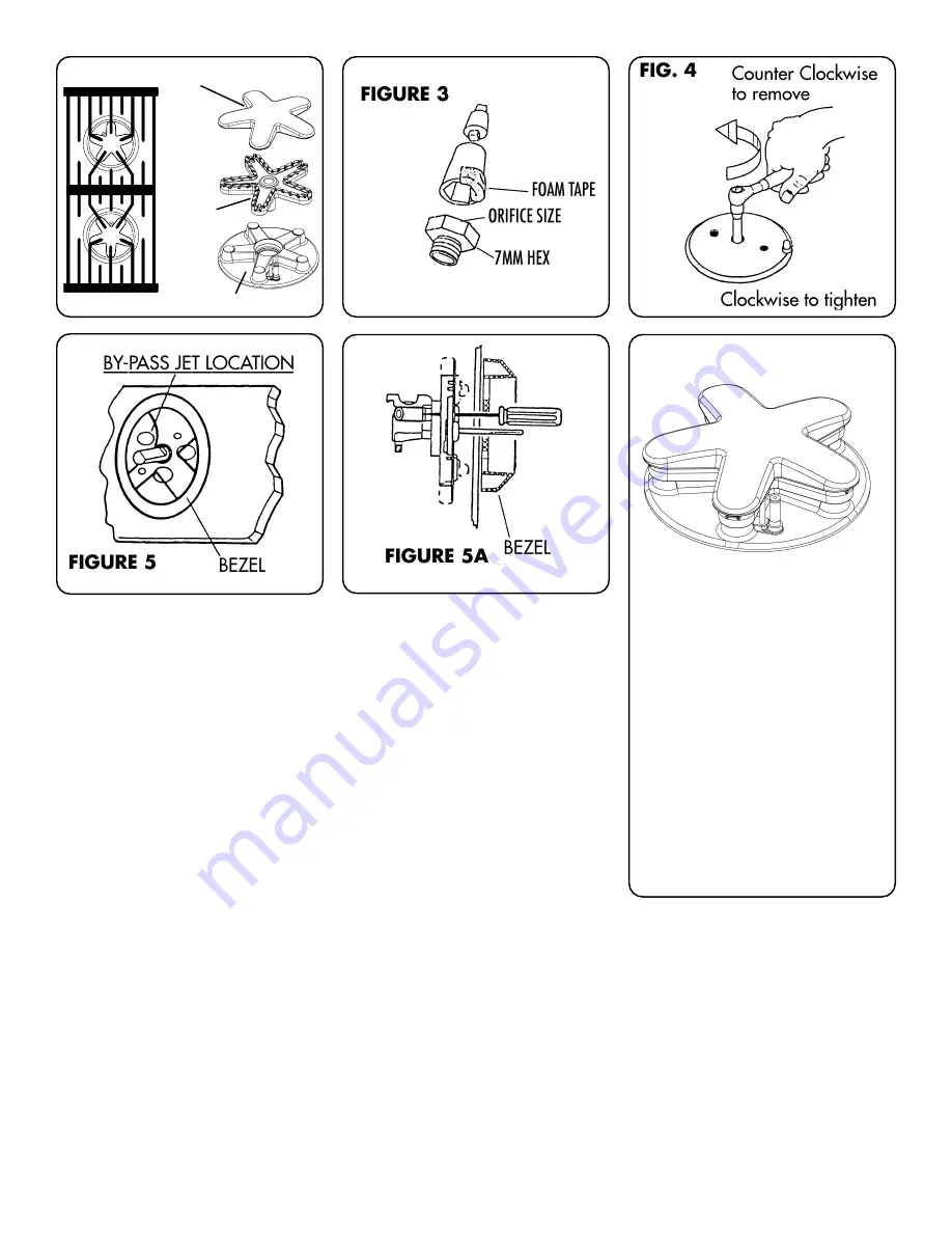
REMOVE GRATES, BURNER CAPS and FLAME SPREADERS (see Fig. 2).
2)
REMOVE MAIN SURFACE BURNER ORIFICES. ( 7mm Hex) This kit con-
tains the orifices and the socket required to remove them. A method of
retaining main orifices in the socket during extraction and insertion is to
apply a piece of foam tape, supplied in the kit, to the socket, as shown in Fig.
3. Insert the socket driver with 3" minimum extension into the jet holders
and remove existing orifices, as shown in Fig. 4.
3)
INSTALL NEW MAIN SURFACE BURNER ORIFICES #168. Tighten ori-
fices until snug.
4)
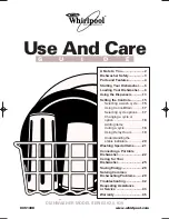
REASSEMBLE. Install flame spreaders and burner caps (See Fig. 8). Replace
grates.
B)
CONVERT VALVES FOR NATURAL GAS
The bypass jet on each valve (see Fig. 5) must be adjusted as follows:
1)
With all KNOBS IN “OFF” POSITION, REMOVE KNOBS.
2)
LOCATE HOLE on control panel which is aligned to bypass screw. (see Fig.
5)
3)
Insert screw driver in hole. TURN Bypass SCREW clockwise until “bot-
tomed out” (approximately 1/8 to3/16 turn), then back out (counter clock-
wise) 1/2 to 3/4 turn. See Fig 5A.
4)
REPLACE KNOBS.
5)
CHECK FOR PROPER FLAME CHARACTERISTICS - Flame should be blue
and stable with no yellow tips on the ends of the flame. See Fig. 6.
FIGURE 2
Burner Cap
Burner Base
Flame
Spreader
Star Grate (Top View)
168
FIGURE 6


