background image

EUROPA SERIES USER MANUAL

8

3.

Safety Information

• 

Operation is subject to the following two conditions: 1 This device may not 

cause harmful interference, and 2 this device must accept any interference 

received, including interference that may cause undesired operation. 

• 

This  device  must  be  installed  by  qualified  service  personnel  or  system 

installation personnel.

• 

Do not disassemble or modify the thermal device. 

If the device operates 

abnormally, please contact the supplier and do not dismantle the device 

on your own.

• 

Do not point the imager (with or without the lens cover) at intensive energy 

sources, e.g. devices that emit laser radiation, or the sun. This can affect 

the accuracy of the camera, and cause damage to the detector. 

• 

Do not use the imager in temperatures higher than 50 °C (122 °F) or lower 

than -15 °C (5 °F). High/low temperatures can cause damage to the device. 

• 

Do not cut, alter, or place heavy items on the device. These actions may 

cause an electric short leading to fire or electrocution.

• 

Prior to start of the device, make sure that the power supply is properly 

connected. If the power supply is connected incorrectly, the device may 

be damaged.

• 

Do not put holes in the device with objects. Damage to the device may occur.

• 

Do  not  hit  the  device  with  a  hammer  or  apply  strong  impacts  or  electric 

shocks to it. Damage to the device may occur.

• 

Do not put the device in or near a fire, stove or other high-temperature 

locations. Damage or ignition of the device may occur.

• 

Do not put the device in direct sunlight or other high-temperature locations. 

Damage or ignition of the device may occur.

• 

Do not get water or salt water on the device or permit the device to get 

wet. Damage to the device may occur.

• 

Remove any water or moisture on the device before you install it. Damage 

to the device may occur.

• 

If there are fluids on the device and the fluid gets into the eyes, do not rub 

the eyes. Flush well with water and immediately get medical care.  

• 

Always  dispose  of  device  in  accordance  with  local,  state  and  federal 

regulations.

• 

Do not use the device if, when used, there is a smoke emitted from the 

device, the device feels excessively hot, changes color, changes shape, or 

is in an unusual condition. Speak with a sales office if one or more of these 

problems occurs. 

• 

Do not use liquids to clean the electronics.

• 

Clean the case with a damp cloth and a weak soap solution. Do not use 

abrasives, isopropyl alcohol, or solvents to clean the case or lens/screen. 

Summary of Contents for Europa 380

Page 1: ...SWITCHING THE UNIT ON IMPORTANT SAFETY INFORMATION INSIDE Shown with a 13 mm lens 855 W Cardinal Dr Suite A Beaumont TX 77705 Phone 409 861 0788 Toll Free 866 861 0788 Thermal Camera cores fall under...

Page 2: ...EUROPA SERIES USER MANUAL 2 Revision History 04 2022 001 Document created...

Page 3: ...ns 6 2 9 Training 7 Safety Information 8 Technical Specifications 10 Lens Options and Model Numbers 14 5 1 Europa 640 Models 14 5 2 Europa 380 Models 15 Structure 16 6 1 Pin Layout 16 6 2 Pin Connecto...

Page 4: ...written permission of Thermal Camera The documentation must not in whole or part be copied photocopied reproduced translated or transmitted to any electronic medium or machine readable form without p...

Page 5: ...heeled bin symbol indicates that waste electrical and electronic equipment should not be discarded together with unseparated household waste but must be collected separately All local authorities have...

Page 6: ...terface options It can be used for a wide range of applications Environment of use UAV UAS integrations handheld and head mounted equipment multi spectral systems industrial monitoring security applic...

Page 7: ...EUROPA SERIES USER MANUAL 7 2 9 Training To read about infrared training visit https infraredtraininginstitute com...

Page 8: ...ly the device may be damaged Do not put holes in the device with objects Damage to the device may occur Do not hit the device with a hammer or apply strong impacts or electric shocks to it Damage to t...

Page 9: ...nough for the condensation to evaporate Keep device out of reach of children This product is a precise electronic device that must be handled with care during use storage and transportation to prevent...

Page 10: ...ity NETD 50 mK 0 05 C at 25 C 77 F Frame Rate 30 Hz PAL or 50 Hz NTSC 1 Dimensions without lens 26 mm x 26 mm x 22 mm L x W x D 0 5 mm 1 02 x 1 02 x 0 87 L x W x H 0 02 2 Power 4V 6V DC 1 3W 3 4V 6V D...

Page 11: ...t 3 5V 18V DC 4 8 bit or 14 bit LVCMOS digital video is supported only on the 70 pin connector module 5 This function is only available in analog video and digital BT 656 Europa 640 Europa 380 Palette...

Page 12: ...voltage Under voltage Reverse Connection Weight without lens 21 g 0 75 oz 3 g 0 11 oz Zoom 1 0X 8 0X continuous zoom 6 Interface RS 232 UART 3 3 V Expansion Board Available Video Analog 1 channel PAL...

Page 13: ...out connector board 4 Wattage is based on tests without extension boards Typical working voltage is 5V DC Expansion components support 3 5V 18V DC 5 8 bit or 14 bit LVCMOS digital video is supported o...

Page 14: ...17 25 mm 1 0 Athermal 17 14 0 480 mrad ICIEuropa640P X 12 ICIEuropa640C 0 12 ICIEuropa640SL 0 12 35 mm 1 0 Athermal 12 5 10 0 340 mrad ICIEuropa640P X 08 ICIEuropa640C 0 08 ICIEuropa640SL 0 08 55 mm...

Page 15: ...CIEuropa380SL 0 44 5 8 mm 1 2 Athermal 44 33 2 060 mrad ICIEuropa380P X 28 ICIEuropa380C 0 28 ICIEuropa380SL 0 28 9 1 mm 1 2 Athermal 28 21 1 310 mrad ICIEuropa380P X 20 ICIEuropa380C 0 20 ICIEuropa38...

Page 16: ...n the connector Users can adopt the Hirose 70 Pin DF40HC 3 0 70DS 0 4V 51 to implement the connection between the thermal camera and user expansion boards 6 Structure 6 2 Pin Connector Interface Descr...

Page 17: ...35 DV11 Data 36 DV10 Data 37 DV13 Data MSB 14 bit 38 DV12 Data 24 DV14 Data Data 23 DV15 Data MSB 16 bit Data MSB BT 1120 39 Line_Valid Line valid signal Line valid signal 40 Frame_Valid Frame valid s...

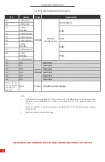
Page 18: ...ending and receiving 3 GND and VGND are shorted internally PLEASE READ AND UNDERSTAND THE TABLES BEFORE SWITCHING THE UNIT ON NO Name Type Description 47 LVDS_CLK Output LVDS_H VCCIO 2 5V Clock Signal...

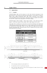
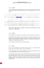
Page 19: ...ded into 10 bit and 14 bit When RAW data or temperature TMP data are produced the data bits are 14 bits namely DV 13 0 where DV0 is LSB and DV13 is the MSB When the user selects the data after the out...

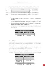
Page 20: ...ts output image processing DRC data CDS_2 is only available for radio metric Europa devices i e Europa 380 and Europa 640 C SL Series devices cannot utilize CDS_2 CDS_2 digital video contains 1 Clock...

Page 21: ...ck Frequency Europa C 380 Europa SL 380 22 500 MHz Europa C 640 Europa SL 640 33 750 MHz Europa 380 11 250 MHz Europa 640 22 500 MHz CDS_2 Clock Frequency Model Clock Frequency Europa 380 22 5 MHz Eur...

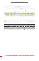
Page 22: ...ER MANUAL 22 Sync Code H0 H1 H2 H3 H4 H5 H6 H7 BLANK LINE 3FFF 0000 0000 2AC0 3FFF 0000 0000 2D80 VALID LINE 3FFF 0000 0000 2000 3FFF 0000 0000 2740 PLEASE READ AND UNDERSTAND THE TABLES BEFORE SWITCH...

Page 23: ...pin DF52 20S 0 8H connector Molex 20 pin 52745 2097 connector Coming Soon Power input 3 5 18 VDC typical 12 VDC RS232 RS422 LVDS_H digital video Analog video 4 keys DF56C 30S 0 3V Coming Soon Power in...

Page 24: ...replace the cloth and repeat operation 9 2 Disinfecting the Camera Surface Do not use corrosive cleaning solutions on the optical glass components Do not get the electronics wet It is recommended to d...

Page 25: ...ntists inspectors and operators in space power companies medical pulp and paper food industry research and development and various process industries Thank you for your dedicated and continued support...

Reviews: