24
Start-Up
Every unit is factory set to deliver chilled water in
accordance with the standard operating
specifications for that particular chiller. Due to
variables involved with different applications and
different installations, minor adjustments may be
required during the initial start-up to ensure proper
operation. Use a qualified refrigeration technician to
perform the start-up procedure in sequence. The
following serves as a checklist for the initial start-up
and for subsequent start-ups if the chiller is out of
service or without power for a prolonged time.
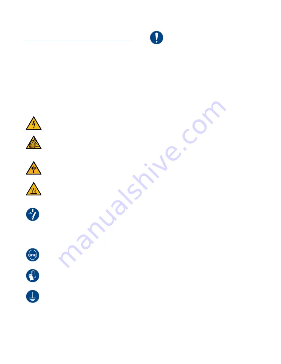
WARNING: This equipment contains hazardous
voltages that can cause severe injury or death.
WARNING: This equipment contains refrigerant under
pressure. Accidental release of refrigerant under
pressure can cause personal injury and or property
damage.
WARNING: This equipment may contain fan blades or
other sharp edges. Make sure all fan guards and other
protective shields are securely in place.
WARNING: The exposed surfaces of motors, refrigerant
piping, and other fluid circuit components can be very
hot and can cause burns if touched with unprotected
hands.
CAUTION: Disconnect and lock out incoming power
before installing, servicing, or maintaining the
equipment. Connecting power to the main terminal
block energizes the entire electric circuitry of the unit.
Electric power at the main disconnect should be shut
off before opening access panels for repair or
maintenance.
CAUTION: Wear eye protection when installing,
maintaining, or repairing the equipment to protect
against any sparks, debris, or fluid leaks.
CAUTION: Wear protective gloves when installing,
maintaining, or repairing the equipment to protect
against any sparks, debris, or fluid leaks.
CAUTION: Wire the unit ground in compliance with
local and national codes.
CAUTION: The unit requires the main power to remain
connected during off-hours to energize the
compressor’s crankcase heater. Disconnect main
power only when servicing the chiller. The crankcase
heater should remain on when the compressor is off to
ensure liquid refrigerant does not accumulate in the
compressor crankcase. Energize main power at least
24 hours prior to startup.
Step 1 – Connect Main Power
Connect main power properly ensuring it matches
the voltage shown on the nameplate of the unit.
Check the electrical phase sequence prior to start-
up. Operation of the compressor with incorrect
electrical phase sequencing will cause damage to the
compressors. Check the phasing prior to applying
power. The proper sequence is “ABC.” If the phasing
is incorrect, open the main power disconnect and
switch two line leads on the main power terminal
blocks (or the unit mounted disconnect). All
electrical components are in-phase at the factory. Do
not interchange any load leads that are from the unit
contactors or the motor terminals. After making
proper power connection and grounding, turn the
main power on for a minimum of 24 hours prior to
startup.
Step 2 – Fill Coolant Circuit
Check to make sure all process chilled-water piping
connections are secure. Open the chiller cabinet and
fill the coolant reservoir with the proper water or
water/glycol solution following the guidelines shown
below. When using a glycol solution only use glycol
with a corrosion inhibitor.
System Fill Water Chemistry Requirements
The properties of water make it ideal for heat
transfer applications. It is safe, non-flammable, non-
poisonous, easy to handle, widely available, and
inexpensive in most industrialized areas.
When using water as a heat transfer fluid it is
important to keep it within certain chemistry limits to
avoid unwanted side effects. Water is a “universal
solvent” because it can dissolve many solid
substances and absorb gases. As a result, water can
cause the corrosion of metals used in a cooling
system. Often water is in an open system (exposed
to air) and when the water evaporates, the dissolved
minerals remain in the process fluid. When the
concentration exceeds the solubility of some
Summary of Contents for Accuchiller KSE
Page 1: ......
Page 2: ......
Page 10: ...4 Figure 3 Mounting Platform Figure 4 Rigging...
Page 37: ...31 Notes...
Page 38: ...32...
Page 39: ......


