7
2.
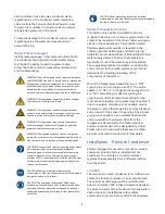
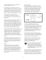
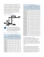
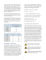
Determine approximate line sizes by referring to
Table 10 for liquid lines and Table 11 for
discharge lines.
3.
Check the line size by calculating the actual
equivalent length using the equivalent lengths
as shown in Table 9.
CAUTION: When calculating the equivalent length, do
not include piping of the chiller unit. Only field piping
must be considered.
Table 1 – Equivalent Lengths of Elbows
Line Size
OD (in)
Equivalent Lengths of Refrigerant Pipe (feet)
90°
Standard
90°
Long
Radius
90°
Street
45°
Standard
45°
Street
7/8
2.0
1.4
3.2
0.9
1.6
1 1/8
2.6
1.7
4.1
1.3
2.1
1 3/8
3.3
2.3
5.6
1.7
3.0
1 5/8
4.0
2.6
6.3
2.1
3.4
2 1/8
5.0
3.3
8.2
2.6
4.5
2 1/8
6.0
4.1
10.0
3.2
5.2
3 1/8
7.5
5.0
12.0
4.0
6.4
3 5/8
9.0
5.9
15.0
4.7
7.3
4 1/8
10.0
6.7
17.0
5.2
8.5
Liquid Line Sizing
The liquid line diameter should be as small as
possible while maintaining acceptable pressure drop.
This is necessary to minimize refrigerant charge. The
total length between the chiller unit and the air-
cooled condenser must not exceed 200 actual feet
or 300 equivalent feet. It is best to pipe the liquid
line so that there is an immediate drop of at least 15
inches at the condenser outlets to make a liquid seal.
Liquid line risers in the system will require an
additional 0.5 psig pressure drop per foot of vertical
rise. When it is necessary to have a liquid line riser,
make the vertical run immediately after the
condenser before any additional restrictions. The
liquid line risers must not exceed 10 feet in height
from the condenser liquid line connection. The liquid
line does not require pitching. Install a pressure tap
valve at the condenser to facilitate measuring
pressure for service.
Liquid lines do not typically require insulation.
However, if exposing the lines to solar heat gain or
temperatures exceeding 110 °F, there is a negative
effect on sub-cooling. In these situations, insulate
the liquid lines.
Table 2 – Liquid Line Size/Circuit (inches OD)
Total
Equivalent
Length (Ft)
Systems Designed for
20°F to 39°F Set Point
Systems Designed for
40°F to 80°F Set Point
50
Ton
75
Ton
100
Ton
125
Ton
50
Ton
75
Ton
100
Ton
125
Ton
25
1 3/8 1 3/8 1 5/8 1 5/8 1 3/8 1 5/8 2 1/8 2 1/8
50
1 3/8 1 3/8 1 5/8 1 5/8 1 3/8 1 5/8 2 1/8 2 1/8
75
1 3/8 1 3/8 1 5/8 1 5/8 1 3/8 1 5/8 2 1/8 2 1/8
100
1 3/8 1 3/8 1 5/8 1 5/8 1 3/8 1 5/8 2 1/8 2 1/8
125
1 3/8 1 3/8 1 5/8 1 5/8 1 3/8 1 5/8 2 1/8 2 1/8
150
1 3/8 1 ⅝ 1 5/8 1 5/8 1 3/8 1 5/8 2 1/8 2 1/8
175
1 3/8 1 ⅝ 1 5/8 1 5/8 1 5/8 2 1/8 2 1/8 2 1/8
200
1 3/8 1 5/8 1 5/8 2 1/8 1 5/8 2 1/8 2 1/8 2 1/8
225
1 3/8 1 5/8 1 5/8 2 1/8 1 5/8 2 1/8 2 1/8 2 1/8
250
1 3/8 1 5/8 2 1/8 2 1/8 1 5/8 2 1/8 2 1/8 2 1/8
275
1 3/8 1 5/8 2 1/8 2 1/8 1 5/8 2 1/8 2 1/8 2 5/8
300
1 3/8 1 5/8 2 1/8 2 1/8 1 5/8 2 1/8 2 1/8 2 5/8
Discharge (Hot Gas) Line Sizing
The discharge line sizes depend on the velocity
needed to obtain sufficient oil return. It is very
important to minimize line length and restrictions to
reduce pressure drop and maximize capacity.
Upflow hot gas risers need to have a trap at the
bottom and reverse trap at the top. In addition, a
trap and reverse trap arrangement needs to be
spaced every 15 feet in the rise for oil management.
Figure 4 – Vertical Riser Traps


