10
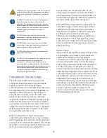
WARNING: The exposed surfaces of motors, refrigerant
piping, and other fluid circuit components can be very
hot and can cause burns if touched with unprotected
hands.
CAUTION: Disconnect and lock out incoming power
before installing, servicing, or maintaining the
equipment. Connecting power to the main terminal
block energizes the entire electric circuitry of the unit.
Electric power at the main disconnect should be shut
off before opening access panels for repair or
maintenance.
CAUTION: Wear eye protection when installing,
maintaining, or repairing the equipment to protect
against any sparks, debris, or fluid leaks.
CAUTION: Wear protective gloves when installing,
maintaining, or repairing the equipment to protect
against any sparks, debris, or fluid leaks.
CAUTION: Wire the unit ground in compliance with
local and national codes.
CAUTION: The unit requires the main power to remain
connected during off-hours to energize the
compressor’s crankcase heater. Disconnect main
power only when servicing the chiller. The crankcase
heater should remain on when the compressor is off to
ensure liquid refrigerant does not accumulate in the
compressor crankcase. Connect main power at least
24 hours prior to initial startup.
Compressor Control Logic
The chiller uses variable capacity control. The
compressor has a slide valve to provide variable
capacity control from 25-100% by directly
controlling the amount of refrigerant gas taken in by
the compressor rotors. The amount of gas taken in
depends on the valve position. The loader and
unloader solenoid valves control the slide valve
position. These valves are pulsed in short time
increments to balance compressor capacity with the
chiller load. The chiller has a minimum compressor
recycle timer to protect the compressor from rapid
cycling. The recycle timer begins once a compressor
starts and will not let that compressor restart until
the recycle timer has timed-out.
When the start button is pressed any pumps
controlled by the chiller will turn on, any condenser
water-regulating valves will open, and the electronic
expansion valve and liquid line solenoid valve for the
lead chiller circuit will open and that compressor will
start. The compressor will run unloaded for
approximately two minutes after which it will
load/unload as required to maintain the fluid set
point temperature. If there are multiple chillers in a
master/slave arrangement, additional compressors
will start and then load/unload as needed.
After pressing the stop button all compressors run
unloaded for approximately 60 seconds and then
shutdown one at a time with a two-second time
delay between compressors. After all compressors
are stopped, all liquid line solenoid valves,
condenser water regulating valves, and electronic
expansion valves in the system close. Any pumps
controlled by the chiller run for 60 seconds and then
stop. The system is now ready to begin the next
startup sequence.
Master/Slave
It is possible to link together multiple chillers to form
a single system, using single or dual compressor
chillers with a maximum of six compressors
connected. Any chiller can be setup to be a master
or a slave. The master chiller controls the staging
order of the compressors and the running demand
of all the compressors in the system in order to
maintain the common chilled water set point. A slave
chiller becomes dependent on the master only for its
compressor staging order and running demand. The
slave chiller PLC performs all other operations. The
chilled water piping must be connected using a
manifold and the supply sensor must be positioned
downstream of all individual chilled water streams to
read a mixed water temperature. Wire the supply
and return water temperature sensors in the
common return chilled water piping to the chiller
PLC designated as the master.


