4
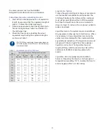
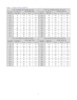
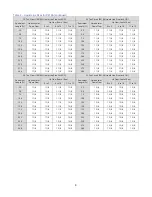
maintain proper flow through the condenser ensure
the condenser water pump supply provide at least
25 psi at a flow of 3 gpm per ton of chiller capacity.
The condenser has a two-way condenser water-
regulating valve to control the amount of water
passing through the condenser, which in turn
maintains the refrigeration pressures in the circuit.
To prevent damage to the condenser and/or water-
regulating valve, the water pressure should not
exceed 150 psig.
Installation – Remote Condenser
Chillers with a remote air-cooled condenser include
a factory-selected remote condenser. The remote
air-cooled condenser typically ships separately from
a different location than the chiller.
The condenser ships on its side with the legs
removed to reduce shipping dimensions and provide
more protection to the coil from possible damage
caused by impact loading over rough roads and
transit conditions.
Location
The condenser is for outdoor use. Locate the remote
condenser in an accessible area with enough space
to allow for easy maintenance and operation. Avoid
locating piping or conduit over the unit to ensure
easy access with an overhead crane or lift to lift out
heavier components during replacement or service.
The vertical air discharge must be unobstructed.
Allow a minimum of 48 inches of clearance on all
sides of the condenser. For installations with multiple
condensers, allow a minimum of 96 inches between
condensers placed side-by-side or 48 inches for
condensers placed end-to-end.
Proper ventilation is important. Locate the condenser
in an area that will not rise above 110°F. Avoid areas
such as an alcove with east, north, and west walls
that can be significantly warmer than surrounding
areas. Locate the condenser where fan noise and
vibration transmission into nearby workspaces is
unlikely.
Install the condenser on a firm, level surface. Avoid
locations near exhaust fans, plumbing vents, flues, or
chimneys. Fasten the mounting legs at their base to
the steel or concrete of the supporting structure.
Lifting
Use qualified personnel when lifting and positioning
the condenser. Lifting brackets or holes are at the
corners for attaching lifting slings. Use spreader bars
when lifting to apply the lifting force vertically.
Under no circumstances use the coil headers or
return bends in the lifting or moving of the
condenser.
Mounting Legs
Assemble the corner legs to the bottom flanges on
the unit side panels and end panels using the
hardware provided and the matching mounting
hole-patterns. All corner legs are the same. For units
that are longer than three fans, assemble the center
leg. Remove two bolts from the bottom flange of the
unit side panels that match the hole-pattern on the
top flanges of both legs. Attached the center legs
using the hardware provided at the center-divider
panel location. Replace the bolts removed from the
side panels to secure the leg assembly to the bottom
flanges of the condenser side panels.
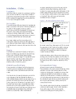
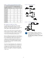
Figure 2 - Mounting Remote Condenser Legs
Interconnecting Refrigerant Piping
The chiller and remote condenser ship with a
nitrogen holding charge. Evacuate this charge before
charging with refrigerant.
The discharge and liquid lines leaving the chiller
have caps. These line sizes do not necessarily reflect
the actual line sizes required for the piping between
the chiller and the air-cooled condenser. Refrigerant
piping size and piping design have a significant
impact on system performance and reliability. All
Corner Leg
Center Leg
(Right-hand Side Facing Header)


