background image


19 

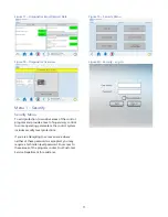
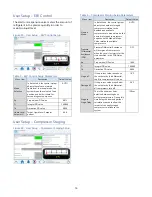
User Setup – Chiller Capacity


Chiller Capacity Screen 

This screen is necessary to adjust the nominal pipe 
size that the flow sensor is inserted into. 
 

Figure 49 - User Setup – Chiller Capacity Setup 


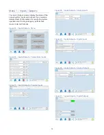
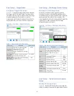
User Setup – Date/Time 

Date/Time Screen 

Date and Time are necessary for accurate data 
logging as well as fault log time stamps. Touch the 
fields for adjustment.  
 

Figure 50 - User Setup – Date / Time Setup 


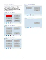
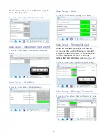
User Setup – Evaporator Valve 

Evaporator Valve Control Screen 

This feature provides the ability to close off 
evaporator fluid flow when a circuit is not in 
operation. This allows for tighter temperature 
control. 
 

Figure 51 - User Setup – Evaporator Valve Control 
Setup  


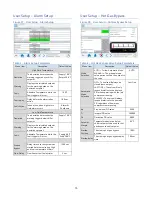
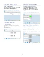
User Setup – Temperature Offsets 

Temperature Offsets Screen 

This screen provides the ability to add an offset to 
the temperature values if any slight deviations in 
temperature readings exist.  
 

Figure 52 - User Setup – Temperature Offset Control 
Setup 


Summary of Contents for Accuchiller TCFW375

Page 1: ......

Page 2: ......

Page 3: ...ndary 5 Control Operation 6 Screen Navigation 6 System Initialization 6 Figure 1 Start Up Splash 6 Home Chiller Home Screen 7 System Overview 7 Figure 2 Chiller Home 7 Table 1 System Overview Function...

Page 4: ...Inputs Outputs 13 Figure 25 Inputs Outputs Menu 13 Figure 26 Inputs Outputs Temperature Inputs 13 Figure 27 Inputs Outputs Pressure Inputs 13 Figure 28 Inputs Outputs Analog Inputs 13 Figure 29 Input...

Page 5: ...s 18 Figure 45 User Setup IP Address Setup 18 User Setup Units 18 Figure 46 User Setup Display Units Setup 18 User Setup Remote Setpoint 18 Figure 47 User Setup Remote Setpoint Setup 18 User Setup Pri...

Page 6: ...Screen 21 Modbus 22 Table 10 Modbus 22 Start Up 23 Step 1 Connect Main Power 23 Step 2 Fill Coolant Circuit 23 Step 3 Condenser Water Temperature and Flow 24 Step 4 Check Refrigerant Valves 24 Step 5...

Page 7: ...We recommend the use of a refrigerant management program to document the type and quantity of refrigerant in the equipment In addition we recommend only licensed and EPA certified service technicians...

Page 8: ...ng the shipping damage claim is the responsibility of the receiving party Do not install damaged equipment without getting the equipment repaired Shipping damage is the responsibility of the carrier T...

Page 9: ...conditions may result in the chiller shutting down due to high refrigerant pressure Allowing the condenser to plug up from contaminants in the condenser water stream adversely affects performance In...

Page 10: ...age at the main power source Voltage must be within the voltage utilization range given on the drawings included with the unit If the measured voltage on any leg is not within the specified range noti...

Page 11: ...start if the process heat load continues to increase after the lead compressor is running and fully loaded Both compressors will share the load and modulate their capacities in order to maintain the...

Page 12: ...assword protected to prevent unintended changes There are two levels of security Username is case sensitive User Level Password 9999 Supervisor Level Password 7720 When navigating screens any user adj...

Page 13: ...tatus Messaging Provides information about any warnings or alarms which may have occurred None Setpoint Modify the Setpoint by touching the current Setpoint on the HMI An authorized security level pas...

Page 14: ...l system Some parameters are password protected The main User level password is for gaining access to changing the main system set point and various other warning and alarm settings A few higher level...

Page 15: ...e above shows there are no alarms in history if an alarm condition previously existed it would appear in this window Warning Glycol If the Chiller Setpoint goes below 45 F the Glycol Warning Screen wi...

Page 16: ...rmation about the various portions of the system Figure 10 Diagnostics Menu 1 Figure 11 Diagnostics Menu 2 Figure 12 Diagnostics Circuit Details Figure 13 Diagnostics Circuit Turbocor Figure 14 Diagno...

Page 17: ...l of supervisory control to some operating parameters the control system includes security level protections If you are attempting to access an area where neither of these passwords is accepted you ma...

Page 18: ...gure 22 Security Edit User Figure 23 Security Delete User Figure 24 Security Change Password Table 2 Security Users and Passwords User Name Password Screen Reference User 9999 None Supervisor 7720 Non...

Page 19: ...itoring system operation and for diagnosing any performance issues or alarms that arise Figure 25 Inputs Outputs Menu Figure 26 Inputs Outputs Temperature Inputs Figure 27 Inputs Outputs Pressure Inpu...

Page 20: ...meters In most cases the factory default settings are sufficient however adjustment of parameters and settings is possible through the User Setup menus Figure 32 User Setup Menu 1 Figure 33 User Setup...

Page 21: ...ypass Delay time once the system has started before monitoring High and Low temperature Alarms 1200 sec Flow Delay Flow Sensor fault delay timer 5 sec User Setup Hot Gas Bypass Figure 38 User Setup Ho...

Page 22: ...Mode In Auto Mode the control system adjusts the number of staged compressors relative to the demand and available compressors In manual mode the number of staged compressors depends on the Manual Mo...

Page 23: ...r regulating valve is standard The valve is a butterfly type valve with a modulating actuator and is located in the condenser water piping at the outlet of the condenser The valve regulates the flow o...

Page 24: ...Address Setup User Setup Units Figure 46 User Setup Display Units Setup User Setup Remote Setpoint When the remote setpoint option is active an incoming 4 20mA or 0 10VDC signal controls the setpoint...

Page 25: ...tment Figure 50 User Setup Date Time Setup User Setup Evaporator Valve Evaporator Valve Control Screen This feature provides the ability to close off evaporator fluid flow when a circuit is not in ope...

Page 26: ...ly start if a power outage has occurred during a run state When active the Automatic Start toggle will indicate Automatic Start Enabled and when not active it will indicate Automatic Start Disabled Us...

Page 27: ...erature and optional hot gas bypass valve resisters if present for easy analysis of the system operation Trending is always enabled and always running Figure 55 System Trending 1 Figure 56 System Tren...

Page 28: ...utRegister 1 2 PLC_VERSION Real InputRegister 3 1 SYSTEM_DEMAND_PERCENT Int InputRegister 4 1 HMI_ALARM_DISPLAY Int InputRegister 5 1 CHILLER_STATUS UInt InputRegister 6 2 CKT1_RFRG_SUCTION_TEMP_HMI R...

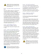
Page 29: ...s incorrect open the main power disconnect and switch two line leads on the main power terminal blocks or the unit mounted disconnect All electrical components are in phase at the factory Do not inter...

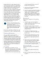
Page 30: ...he Low Temperature Fault to the appropriate setting CAUTION The manufacturer s warranty does not cover the evaporator from freezing It is vital that the Evaporator Low Temperature Fault is set properl...

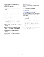
Page 31: ...y reduced downtime reduced repair costs and an extended useful lifetime for the chiller Any monetary costs of implementing these procedures will usually more than pay for itself Once a Week 1 Check to...

Page 32: ...dust build up and clean if necessary 19 Check calibration of temperature pressure sensors 20 Check operation of the inlet guide vane IGV assembly Once Every 5 years Repeat items 1 through 20 and conti...

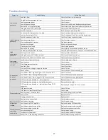
Page 33: ...t out Insufficient refrigerant charge Check refrigerant charge Faulty sensor Check sensor Fluid temperatures too low Check set points Low fluid flow Check fluid flow Compressor does not power up No Lo...

Page 34: ...mperature set points Faulty chilled water temperature sensors Check chilled water temperature sensors No main power Check power at terminal block Low water flow Check water flow Drawings We have prepa...

Page 35: ......

Page 36: ...Sales Customer Service Parts Department 847 966 2260 info thermalcare com 847 966 2260 847 966 2636 847 966 8560 847 966 9358 fax www thermalcare com sales thermalcare com service thermalcare com tcp...

Reviews: