A40i, A60i
Manual 0-5466
INSTALLATION
3T-1
SECTION 3 TORCH:
INSTALLATION
3T.01 Torch Connections
If necessary, connect the torch to the Power Supply.
Connect only the Thermal Dynamics model SL60,
SL60QD™ or SL100 / Mechanical Torch to this power
supply. Maximum torch leads length is 100 feet / 30.5
m, including extensions.
WARNING
Disconnect primary power at the
source before connecting the torch.
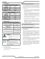
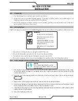
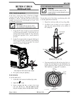
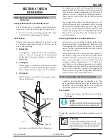
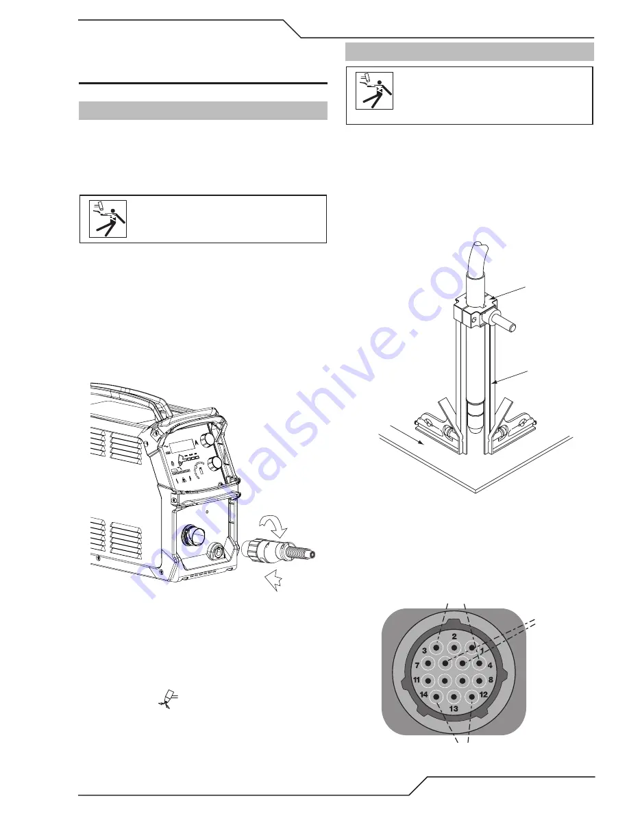
1. Align the ATC male connector (on the torch lead)
with the female receptacle. Push the male con-
nector into the female receptacle. The connectors
should push together with a small amount of
pressure.
2. Secure the connection by turning the locking nut
clockwise until it clicks. DO NOT use the locking
nut to pull the connection together. Do not use
tools to secure the connection.
1
2
Art # A-13286
Connecting the Torch to the Power Supply
3. The system is ready for operation.
Check Air Quality
To test the quality of air:
1. Put the ON / OFF switch in the ON (Left) position.
2. Select SET
mode.
3. Place a welding filter lens in front of the torch
and turn ON the air.
Do not start an arc!
Any oil or moisture in the air will be visible on the lens.
3T.02 Setting Up Mechanical Torch
WARNING
Disconnect primary power at the
source before disassembling the torch
or torch leads.
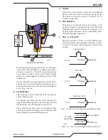
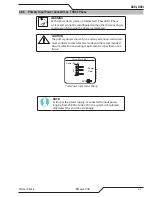
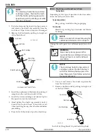
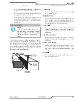
The mechanical torch includes a positioning tube with
rack and pinch block assembly.
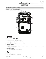
1. Mount the torch assembly on the cutting table.
2. To obtain a clean vertical cut, use a square to
align the torch perpendicular to the surface of
the workpiece.
A-02585
Workpiece
Square
Pinch Block
Assembly
Mechanical Torch Set - Up
3. The proper torch parts (shield cup, tip, start car-
tridge, and electrode) must be installed for the
type of operation. Refer to Section "4T.01 Torch
Parts Selection" on page 4T-1 for details.
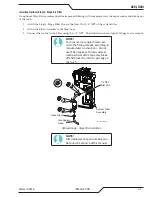
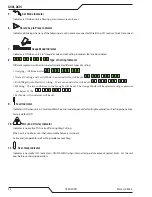
Art # A-08323_AB
Plasma
Start / Stop
Signal
Cutting Machine
OK to Move
Divided
Arc
Voltage
Summary of Contents for A40i
Page 6: ...This Page Intentionally Blank...
Page 8: ...This Page Intentionally Blank...
Page 12: ...TABLE OF CONTENTS This Page Intentionally Blank...
Page 16: ...A40i A60i WARRANTY INFORMATION Manual 0 5466 W 2 This Page Intentionally Blank...
Page 24: ...A40i A60i INTRODUCTION Manual 0 5466 2T 4 This Page Intentionally Blank...
Page 32: ...A40i A60i INSTALLATION Manual 0 5466 3 8 This Page Intentionally Blank...
Page 34: ...A40i A60i INSTALLATION Manual 0 5466 3T 2 This Page Intentionally Blank...
Page 80: ...A40i A60i OPERATION Manual 0 5466 4T 36 This Page Intentionally Blank...
Page 95: ...A40i A60i Manual 0 5466 PARTS LIST 6 3 This Page Intentionally Blank...
Page 99: ...A40i A60i Manual 0 5466 PARTS LIST 6 7 A 07994_AB 1 4 2 3 5 6 7 8 9 10 12 11 10 13...
Page 110: ...A40i A60i APPENDIX Manual 0 5466 A 10 APPENDIX 8 SYSTEM SCHEMATIC 400V 3PHASE CE Art A 13478...
Page 111: ...A40i A60i Manual 0 5466 APPENDIX A 11 Art A 13478...
Page 112: ...A40i A60i APPENDIX Manual 0 5466 A 12 APPENDIX 9 SYSTEM SCHEMATIC 208 480V 3PHASE Art A 13479...
Page 113: ...A40i A60i Manual 0 5466 APPENDIX A 13 Art A 13479...
Page 115: ...This Page Intentionally Blank...

