background image

OPERATION

4-6

Manual 0-2782

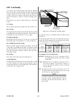
4.05 Cut Quality

Cut quality requirements differ depending on applica-
tion.  For instance, nitride build-up and bevel angle may
be major factors when the surface will be welded after
cutting.  Dross-free cutting is important when finish cut
quality is desired to avoid a secondary cleaning opera-
tion.

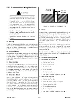
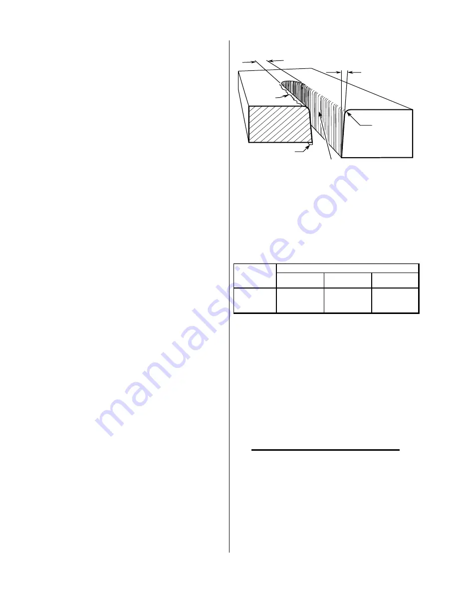
The following cut quality characteristics are illustrated
below:

Cut Surface

The condition (smooth or rough) of the face of the cut.

Bevel Angle

The angle between the surface of the cut edge and a plane
perpendicular to the surface of the plate.  A perfectly per-
pendicular cut would result in a 0° bevel angle.

Top-Edge Rounding

Rounding on the top edge of a cut due to wearing from
the initial contact of the plasma arc on the workpiece.

Dross Build-up and Top Spatter

Dross is molten material which is not blown out of the
cut area and re-solidifies on the plate.  Top spatter is dross
which accumulates on the top surface of the workpiece.
Excessive dross may require secondary clean-up opera-
tions after cutting.

Kerf Width

The width of material removed during the cut.

Nitride Build-up

Nitride deposits which may remain on the surface of the
cut when nitrogen is present in the plasma gas stream.
Nitride buildups may create difficulties if the material is
welded after the cutting process.

Kerf Width

Cut Surface

Bevel Angle

Top Edge

Rounding

Cut Surface

Drag Lines

Dross

Build-Up

Top

Spatter

A-00007

Figure 4-8  Cut Quality Characteristics

Cut quality will vary on different types of and material
thicknesses.

The following table shows the cut quality that can be ex-
pected from this equipment for materials with a thick-
ness from gauge to 3/4 inch (19.1mm):

T yp e   o f   M a t e r ia l

G a s

C a r b o n

S t ee l

S t ain les s

S t ee l

A lu m in u m

A i r

G o o d  -

E x c e l l e n t

G o o d  -

E x c e l l e n t

G o o d  -

E x c e l l e n t

N i tr o g e n

G o o d

G o o d

G o o d 

Description of Cut Characteristics

Excellent

 - Minimum bevel (0 - 4°), minimum kerf (2 x

tip orifice diameter), little or no dross, smooth
cut surface.

Good

 - Slight bevel (0 - 10°), slightly wider kerf (2-1/2 x

tip orifice diameter), some dross (easily re-
moved), medium-smooth cut surface, slight top
edge rounding.

Fair

 - Excessive bevel (over 10°), wide kerf (over 2-1/2 x

tip orifice diameter), medium to heavy dross, rough
cut surface, top edge rounding.

NOTES

Cut quality depends heavily on set-up and param-
eters such as torch standoff, alignment with the
workpiece, cutting speed, gas pressures, and op-
erator ability.

Summary of Contents for CE PAKMaster 75 XL Plus

Page 1: ...July 7 2003 Manual No 0 2782 Operating Manual Plasma Cutting Power Supply CE PAKMaster 75 XLTM Plus A 02464 ...

Page 2: ......

Page 3: ...or omission in this Manual whether such error results from negligence accident or any other cause Printed in the United States of America Publication Date July 7 2003 Record the following information for Warranty purposes Where Purchased ____________________________________ Purchase Date _______________________________________ Power Supply Serial _______________________________ Torch Serial ______...

Page 4: ...General Description of System 2 1 2 03 Specifications Design Features 2 1 2 04 Power Supply Options and Accessories 2 2 SECTION 3 INSTALLATION 3 1 3 01 Introduction 3 1 3 02 Site Selection 3 1 3 03 Unpacking 3 1 3 04 Lifting Options 3 1 3 05 Input Power Cable Connections 3 2 3 06 Gas Connections 3 2 3 07 Connecting Torch Leads 3 4 3 08 Ground Connections For Mechanized Applications 3 9 3 09 Tip Sa...

Page 5: ...eplacement 5 6 SECTION 6 PARTS LISTS 6 1 6 01 Introduction 6 1 6 02 Ordering Information 6 1 6 03 Complete Power Supply Replacement 6 2 6 04 Replacement Parts 6 2 6 05 Options and Accessories 6 2 APPENDIX 1 INPUT WIRING REQUIREMENTS A 1 APPENDIX 2 SEQUENCE OF OPERATION w BLOCK DIAGRAM A 2 APPENDIX 3 MAINTENANCE SCHEDULE A 3 APPENDIX 4 DATA TAG INFORMATION A 4 APPENDIX 5 SYSTEM SCHEMATIC A 6 ...

Page 6: ......

Page 7: ...p your head out of the welding fume plume Use an air supplied respirator if ventilation is not adequate to remove all fumes and gases The kinds of fumes and gases from the plasma arc depend on the kind of metal being used coatings on the metal and the different processes You must be very careful when cutting or welding any met als which may contain one or more of the follow ing Antimony Chromium M...

Page 8: ...ons in this manual PLASMAARC RAYS PlasmaArc Rays can injure your eyes and burn your skin The plasma arc process produces very bright ultra violet and infra red light These arc rays will damage your eyes and burn your skin if you are not properly protected To protect your eyes always wear a welding hel met or shield Also always wear safety glasses with side shields goggles or other protective eye w...

Page 9: ...American National Standards Institute 1430 Broadway New York NY 10018 1 04 Note Attention et Avertissement Dans ce manuel les mots note attention et avertissement sont utilisés pour mettre en relief des informations à caractère important Ces mises en relief sont classifiées comme suit NOTE Toute opération procédure ou renseignement général sur lequel il importe d insister davantage ou qui contribu...

Page 10: ...lesser ou même tuer Le procédé au jet de plasma requiert et produit de l énergie électrique haute tension Cette énergie électrique peut produire des chocs graves voire mortels pour l opérateur et les autres personnes sur le lieu de travail Ne touchez jamais une pièce sous tension ou vive portez des gants et des vêtements secs Isolez vous de la pièce de travail ou des autres parties du circuit de s...

Page 11: ...que les décibels le bruit ne dépassent pas les niveaux sûrs Pour des renseignements sur la manière de tester le bruit consultez l article 1 page 5 1 06 Documents De Reference Consultez les normes suivantes ou les révisions les plus récentes ayant été faites à celles ci pour de plus amples renseignements 1 OSHA NORMES DE SÉCURITÉ DU TRAVAILET DE PROTECTION DE LA SANTÉ 29CFR 1910 disponible auprès d...

Page 12: ...ÉCURITÉ POUR LE SOUDAGE ET LA COUPE disponible auprès de l Association des Normes Canadiennes Stan dards Sales 178 Rexdale Boulevard Rexdale Ontario Canada M9W 1R3 13 Livret NWSA BIBLIOGRAPHIE SUR LA SÉCURITÉ DU SOUDAGE disponible auprès de l Association Nationale de Fournitures de Soudage National Welding Supply Association 1900 Arch Street Philadelphia PA 19103 14 Norme AWSF4 1 de l Association ...

Page 13: ...welding equipment UL Underwriters Laboratory rating 94VO flammability testing for all printed circuit boards used CENELEC EN50199 EMC Product Standard for Arc Welding Equipment ISO IEC 60974 1 BS 638 PT10 EN 60 974 1 EN50192 EN50078 applicable to plasma cutting equipment and associ ated accessories For environments with increased hazard of electrical shock Power Supplies bearing the S mark conform...

Page 14: ...e as follows with the exception of XL Plus Series CutMaster Series Cougar and DRAG GUN A maximum of three 3 years from date of sale to an authorized distributor and a maximum of two 2 years from date of sale by such distributor to the Purchaser and with the further limitations on such two 2 year period see chart below The limited warranty period for XL Plus Series and CutMaster Series shall be as ...

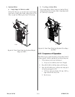
Page 15: ...supply options and accesso ries A 02462 Torch and Leads Work Cable and Clamp XL PLUS Power Supply Pak Master 75XL PLUS CE System The system provides a maximum 1 inch 25 4 mm cut capacity Torch heads are available in various configura tions Torch leads are available in various lengths with fittings for simple installation Spare Parts Kits are avail able for the torches which provide an assortment o...

Page 16: ...Filters moisture and particulate mat ter from the air stream to at least 5 0 microns C High Pressure Regulators High pressure regulators are available for air and ni trogen The regulators are used to set the proper pres sure for the type gas being used NOTE Regulators should not be installed with options A or B above D Multi Purpose Cart Rugged steel cart on easy rolling rear wheels and front moun...

Page 17: ...s to the front panel controls minimum 6 inches or 150 mm CAUTION Operation without proper air flow will inhibit proper cooling and reduce duty cycle 3 03 Unpacking Each component of the system is packaged and protected with a carton and packing material to prevent damage during shipping l Unpack each item and remove any packing material NOTE The Cutting Spare Parts Kit is shipped in the Torch Lead...

Page 18: ... 3 06 Gas Connections A Gas Requirements WARNING This unit not to be used with oxygen O2 Gases Compressed Air or Nitrogen N2 Only Pressure 60 75 psi 4 1 5 2 bar CAUTION Maximum input gas pressure must not exceed 125 psi 8 6 bar Flow Cutting 300scfhstandardcubicfeet hour 142lpm Gouging 300 scfh 142 lpm B Checking Air Quality To test the quality of air place the RUN SET LATCH switch to SET position ...

Page 19: ...ts own filter it is recommended the optional Single Stage Filter or optional Two Stage Air Line Filter be installed for improved filtering Gas connections to optional fil ters are shown in Figures 3 2 and 3 3 Single Stage Air Filter Kit or Two Stage Filter Kit As sembly A 02607 1 4 NPT to 4 6mm Hose Fitting Air Line Filter Assembly 4 6mm Gas Supply Hose Hose Clamp Figure 3 2 Gas Connection to Opti...

Page 20: ... connecting the Torch Leads to the Power Supply are different depending on the type of leads This sub section covers connecting the Torch for the following applications A Hand Systems B Machine Systems Unshielded Leads C Machine Systems Shielded Leads The Torch Leads must be properly installed to the Power Supply for proper operation If the torch leads were not factory installed make all torch con...

Page 21: ... to the bulkhead connection inside the Power Supply Adapter Supplied With Power Supply Pilot Lead Torch Lead Assembly Negative Plasma Lead Adapter Connector Pilot Lead Stud Negative Plasma Lead Connection A 02825 Control PIP Circuit Connectors Figure 3 6a Torch Lead Connections Leads with Two Control Wires Pilot Lead Torch Lead Assembly Negative Plasma Lead Adapter Connector Pilot Lead Stud Negati...

Page 22: ...g the connector out the hole in the front panel of the Power Supply c Feed the end of the torch lead and the Strain Relief into the hole in the unit while routing the single black wire into the notch of the Strain Relief d Tighten the Strain Relief Nut to secure the Strain Relief to the Power Supply Adapter Supplied With Power Supply Pilot Lead Torch Lead Assembly Negative Plasma Lead Adapter Conn...

Page 23: ...e connector out the hole in the front of the Power Supply c Feed the end of the torch lead and the Strain Relief into the hole in the unit while routing the single black wire into the notch of the Strain Relief d Tighten the Strain Relief Nut to secure the Strain Relief to the Power Supply Adapter Supplied With Power Supply Pilot Lead Torch Lead Assembly Negative Plasma Lead Adapter Connector Pilo...

Page 24: ... Nut to secure the Strain Relief to the Power Supply 5 Connect the Negative Plasma lead to the bulk head connection inside the power supply 6 Connect the control circuit connectors on the Torch Leads to the mating connectors on the Remote Pendant Adapter and Power Supply Adapter see Warning WARNING There are two additional connectors that are not used and must be taped out of the way to prevent co...

Page 25: ...ng table is connected with 1 0 AWG European 50 mm2 or larger wire to a good earth ground refer to paragraph C Creating An Earth Ground The ground rod must be placed as close as possible to the cutting table ideally less than 10 ft 3 0 m but no more than 20 ft 6 1 m NOTE All ground wires should be as short as possible Long wires will have increased resistance to RF frequencies Smaller diameter wire...

Page 26: ...h may cause more interference than with no shield at all C Creating An Earth Ground 1 To create a solid low resistance earth ground drive a 1 2 in 12 mm or greater diameter copper clad ground rod at least 6 8 ft 1 8 2 4 m into the earth so that the rod contacts moist soil over most of its length Depending on location a greater depth may be re quired to obtain a low resistance ground see NOTE Groun...

Page 27: ...rference 3 09 Tip Saver Drag Sensing Circuit This power supply is equipped with a Tip Saver Drag Cut Sensing Circuit which reduces current to 35 amps if the tip touches the workpiece The purpose of this is to prolong the life of the tip If the user does not want the current to be decreasedwhen the tip touches the workpiece the sensing circuit can be defeated by closing switch SW1 1 on the Gate Log...

Page 28: ...INSTALLATION 3 12 Manual 0 2782 ...

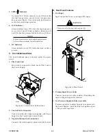
Page 29: ...ea Bracket connected to the side panel of the unit for use in storing the torch torch leads work cable and spare parts kit when not in use The spare parts kit fits into the opening on the top of the bracket The torch leads and work cable wrap around the bracket for easy stor age B Control Panel Features A A 03625 15 40 60 1 2 3 4 5 6 7 Figure 4 2 Operating Controls 1 Current Control A Adjustment t...

Page 30: ...ated under the access panel 1 Pilot Lead Stud Stud used to connect the Torch Leads Pilot Lead to the Power Supply 2 1 3 A 00923 Figure 4 3 Torch Panel Connections 2 Control Cable Connector Used to interface the Adapter supplied with Power Supply to the Torch Leads Control Cable 3 Negative Plasma Lead Connection Connects the torch negative plasma lead to the unit D Rear Panel Features 1 Gas Input I...

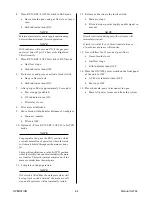
Page 31: ...ture and con taminants from the air stream when using compressed air Filters to 5 0 microns A 01152 1 3 4 2 Figure 4 6 Rear Panel Showing Optional Two Stage Air Filter 4 03 Sequence of Operation The following is a typical sequence of operation for this cutting system Refer to Appendix 2 for a block diagram 1 Close main power source disconnect a AC power is available at the Power Supply 2 Place RUN...

Page 32: ... provides normal touch operation where the torch switch must be held throughout the main arc trans fer For specific applications use the LATCH position where the torch switch can be released after the main arc transfer The torch remains activated until the main arc breaks from the workpiece 11 Complete cutting operation NOTE If the torch is lifted from the workpiece while still having torch switch...

Page 33: ...r a solid and clean work cable connection to the workpiece The area must be free from paint and rust Make a solid work cable connection to the work piece or cutting table A 00925 Figure 4 7 Work Cable Connection To Workpiece E Torch Connection Check that the torch is properly connected F Power Supply On Move the ON OFF switch to ON position G Select Output Current Select the desired current output...

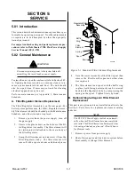
Page 34: ...ide deposits which may remain on the surface of the cut when nitrogen is present in the plasma gas stream Nitride buildups may create difficulties if the material is welded after the cutting process Kerf Width Cut Surface Bevel Angle Top Edge Rounding Cut Surface Drag Lines Dross Build Up Top Spatter A 00007 Figure 4 8 Cut Quality Characteristics Cut quality will vary on different types of and mat...

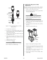
Page 35: ...urn off the gas supply 2 Unscrew the plastic bowl on the bottom of the Fil ter Regulator Assembly The filter element will be visible and still attached to the main body of the Filter Regulator 3 Grasp the filter element and unscrew it from the Filter Regulator body The filter element will come off with a spool and some additional pieces Regulator Filter Assembly Spool Bowl Spring Filter Element Ba...

Page 36: ... part is an option and may not be installed on all units See Section 6 for replacement element catalog number 1 Remove power from power supply 2 Shut off air supply and bleed down system before changing Filter Elements WARNING Always turn off the air supply and bleed the sys tem before disassembling the Filter Assembly as injury could result 3 Loosen the two bolts on the top of the Filter As sembl...

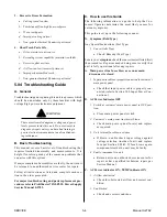
Page 37: ... gas stream swirls as it leaves the torch to maintain a smooth column of gas This swirl effect results in one side of a cut being more square than the other Viewed along the direction of travel the right side of the cut is more square than the left Refer to Fig ure 5 2 To make a square edged cut along an inside di ameter of a circle the torch should move counterclock wise around the circle To keep...

Page 38: ...replacement pro cedures refer to PAK Master 75XL PLUS Power Supply Service Manual 0 2783 C How to use this Guide The following information is a guide to help the Cus tomer Operator determine the most likely causes for various symptoms This guide is set up in the following manner X Symptom Bold Type Any Special Instructions Text Type 1 Cause Italic Type a Check Remedy Text Type Locate your symptom ...

Page 39: ...pair per Torch Instruction Manual F Low cutting output with no control 1 Torch tip touching workpiece tip saver active 2 Incorrect setting of CURRENT control a Check and adjusted to proper setting 3 Faulty components in unit a Return for repair or have qualified technician repair per Service Manual G Erratic or improper cutting output 1 Poor input or output connections a Check all input and output...

Page 40: ... the Left Side Panel up and away from the unit to gain access to the inside of the unit 3 To reinstall the left side panel do the following a Place the left side panel onto the frame and slide the top edge under the lip on the top of the right side panel b Reinstall all the screws to secure the left side panel B Fuse Replacement 1 Remove the left side panel per paragraph A above 2 Locate the inter...

Page 41: ...OTE Parts listed without item numbers are not shown but may be ordered by the catalog number shown B Returns If a product must be returned for service contact your distributor Materials returned without proper authori zation will not be accepted 6 02 Ordering Information Order replacement parts by catalog number and complete description of the part or assembly as listed in the parts list for each ...

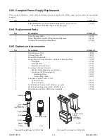
Page 42: ...doff Cutting Guide 8 7575 1 Single Stage Air Line Filter Kit Includes Filter And Hose 7 7507 1 Filter Body 9 7740 2 Filter Element 9 7741 1 Filter Hose not shown 9 7742 1 Two Stage Air Line Filter Kit 7 7500 1 Bracket Filter Mounting not shown 9 7535 1 Two Stage Air Filter Assembly 9 7527 1 First Stage Filter 9 1021 1 Second Stage Filter 9 1022 Computer Control Cable CNC 1 25 Foot 7 6 m 8 5557 1 5...

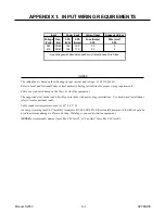
Page 43: ...r hard wired installations refer to local or national codes Cable conductor temperature used is 167 F 75 C An energy limiting fuse UL Class RK 1 examples BUSS LPS LPN RK or Gould Shawmut AZK A6K should be used to minimize damage to Plasma Cutting Welding or power distribution equipment NEVER use replaceable element fuses like UL Class H or one time fuses like UL Class K5 Current Input Suggested Si...

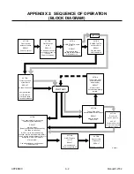
Page 44: ...ain arc will transfer After post flow Gas solenoid closes gas flow stops GAS indicator off ACTION Open external disconnect RESULT No power to system ACTION Close external disconnect switch RESULT Power to system ACTION RUN SET LATCH switch to SET RESULT Gas solenoid open gas flows to set pressure GAS indicator on ACTION Torch moved away from work while still activated RESULT Main arc stops Pilot a...

Page 45: ... supply and pressure flow 4 Purge plasma gas line to remove any moisture build up 5 Inspect input power cable for damage or exposed wires replace if necessary Weekly or Every 30 Cutting Hours 1 Check fan for proper operation and adequate air flow 2 Blow or vacuum dust and dirt out of the entire machine CAUTION Do not blow air into the power supply during cleaning Blowing air into the unit can caus...

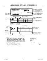
Page 46: ...cycle values Second row Rated cutting current values Third row Conventional load voltage values I A 03288 Output Range Amperage Voltage Type of Power Supply Note 1 Output Current Type Rated No Load Voltage Plasma Cutting Symbol Manufacturer s Name and or Logo Location Model and Revision Level Serial Number and Production Code Conventional Load Voltage Regulatory Standard Covering This Type of Powe...

Page 47: ...Manual 0 2782 A 5 APPENDIX This page left blank ...

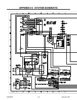
Page 48: ...APPENDIX A 6 Manual 0 2782 APPENDIX 5 SYSTEM SCHEMATIC A 02638 ...

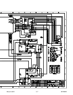
Page 49: ...Manual 0 2782 A 7 APPENDIX A 02638 ...

Page 50: ......

Reviews: