SERVICE
5-6
Manual 0-2782
5.05 Power Supply Parts
Replacement
WARNING
Disconnect primary power to the system before dis-
assembling the torch, leads, or power supply.
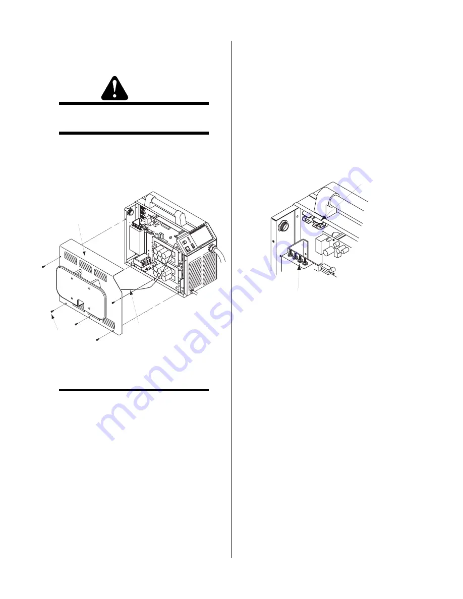
A. Left Side Panel Removal
1.
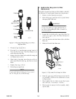
Remove the screws which secure the left side panel
(viewed from front of unit) to the frame assembly.
Left Side
Panel
Screws
(5 places)
Ground
Wire
A-02648
Figure 5-5 Left Side Panel Removal
NOTE
There is a ground wire connection to the Left Side
Panel on the inside of the unit. There is no need to
disconnect the ground wire.
2.
Carefully pull the Left Side Panel up and away
from the unit to gain access to the inside of the
unit.
3.
To reinstall the left side panel do the following:
a. Place the left side panel onto the frame and
slide the top edge under the lip on the top of
the right side panel.
b. Reinstall all the screws to secure the left side
panel.
B. Fuse Replacement
1.
Remove the left side panel per paragraph "A"
above.
2.
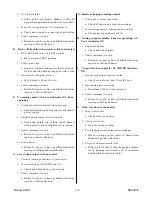
Locate the internal fuse above the input power con-
tactor on the left side of the unit.
3.
Replace the fuse. See Section 6, Parts Lists, for re-
placement fuse catalog number.
4.
Reinstall the left side panel per paragraph "A"
above.
Internal Fuse
0.8 Amps, 600V
A-02613
EMC Filter
Figure 5-6 Internal Fuse Location
This completes the replacement procedures.
Summary of Contents for CE PAKMaster 75 XL Plus
Page 2: ......
Page 6: ......
Page 28: ...INSTALLATION 3 12 Manual 0 2782 ...
Page 47: ...Manual 0 2782 A 5 APPENDIX This page left blank ...
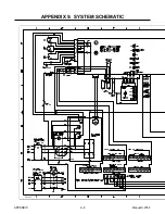
Page 48: ...APPENDIX A 6 Manual 0 2782 APPENDIX 5 SYSTEM SCHEMATIC A 02638 ...
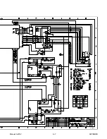
Page 49: ...Manual 0 2782 A 7 APPENDIX A 02638 ...
Page 50: ......

