Operating Manual 0-2682
11
DRAG-GUN Plasma Cutter
B. Input/Output Specifications
B. Input/Output Specifications
B. Input/Output Specifications
B. Input/Output Specifications
B. Input/Output Specifications
Model
Hz
Input
Amps
RMS
Output
Amps
(DC)
Output
Voltage
(DC)
Duty
Cycle %
100/110V 50/60
25/24
12
85
30
120V *
50
22
12
95
30
120V 60
20
12
70
30
220V *
50
13
12
85
30
208/230V 60
10
12
78
30
* CE approved.
2.4 Dimensions
2.4 Dimensions
2.4 Dimensions
2.4 Dimensions
2.4 Dimensions
16.0 in
(406 mm)
9.0 in
(229 mm)
10.0 in.
(254 mm)
A-02004
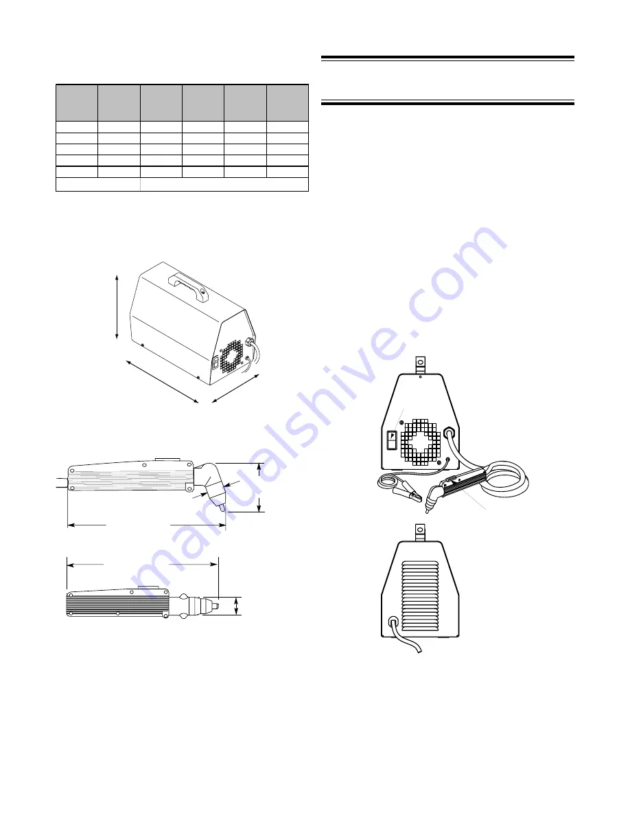
Figure 2-3 Power Supply Dimensions
8 in (203 mm)
1.1 in (27 mm)
2.9 in
(75 mm)
8.9 in (226 mm)
1.1 in
(27 mm)
A-02385
180˚
70˚
Figure 2-4 Torch Dimensions
3.0 CONTROLS:
3.0 CONTROLS:
3.0 CONTROLS:
3.0 CONTROLS:
3.0 CONTROLS:
LOCATION & FUNCTION
LOCATION & FUNCTION
LOCATION & FUNCTION
LOCATION & FUNCTION
LOCATION & FUNCTION
A. Front Panel
A. Front Panel
A. Front Panel
A. Front Panel
A. Front Panel
1. Primary Power ON/OFF Switch
ON position supplies the AC power to activate all sys-
tem control circuits. OFF position deactivates control
circuits. In ON position, this switch is lighted; in the
OFF position, there is no light.
2. Torch & Leads
Torch & leads (including torch tip, gas distributor, elec-
trode, shield cup), are factory installed, ready to cut.
The torch handle (Arc ON/OFF) switch controls the
arc. Push the switch to activate the arc; release the
switch to stop the arc.
3. Work Cable & Clamp
The work cable & clamp are factory installed. Attach
the work cable to the workpiece before cutting.
Rear Panel
Primary Input
Power Cable
Front Panel
PCH 10 Torch
& Leads
Work Cable
& Clamp
Power
ON/OFF
Switch
A-02005
Arc ON/OFF
Switch
Figure 3-1 Front & Rear Panel Controls
B. Rear Panel
B. Rear Panel
B. Rear Panel
B. Rear Panel
B. Rear Panel
1. Primary Input Power Cable
Summary of Contents for Drag-gun
Page 2: ......


