Rev 1.4 09/13/16
4
IMPORTANT
CONSULT LOCAL AND NATIONAL ELECTRICAL CODES FOR ANY SPECIAL
REQUIREMENTS OR RESTRICTIONS BEFORE INSTALLING HALOGUARD
TM
.
5.
LED Indicators, Pushbuttons, LCD Display, and Relays
a. AUTO/MAN Push-button - In the AUTO mode, the Haloguard
TM
II automatically scans all
active channels in sequence. Manual mode is initiated by pushing the MAN push-button. In
the MAN mode, monitor remains locked in a single channel until manually sequenced to
another channel, by pushing MAN push-button. After 2 minutes, sequencer will
automatically default to AUTO mode.
b. TEST Push-button -When depressed alarm relays, lights, audible and remote devices (if
equipped) will activate. Analog outputs will go full scale
c. ZERO Push-button - Reads sensor output and sets this value equal to “zero” ambient
condition. ZERO function is inactive when in ANY alarm condition or during RESET (See
Calibration 3c).
d. OFFSCALE Alarm LED and Relay - Factory set at a value 2 - 3 times the full scale.
e. HI ALARM/ LO ALARM LEDs and Relays - User adjustable 10% to 100% of Full-scale
value (See Calibration 4.0).
Note: Optional TWA Integration activates LO Alarm LED and relay.
f. FAULT LED and Relay - Indicates power failure, out of calibration or sensor failure.
g. POWER LED indicates Haloguard
TM
is receiving power.
h. RESET Pushbutton and LED - indicates Haloguard
TM
in 20 minute RESET mode. During
RESET mode all alarm relays, audible and visual alarms are disabled. Alarms are
automatically enabled if alarm condition is not corrected in 20 minutes. Reset is
automatically initiated on power up.
RESET mode is automatically initiated on power up and whenever power is disrupted (unless
Haloguard Controller is equipped with battery back-up).
10
1/2
”
7
1/8
”
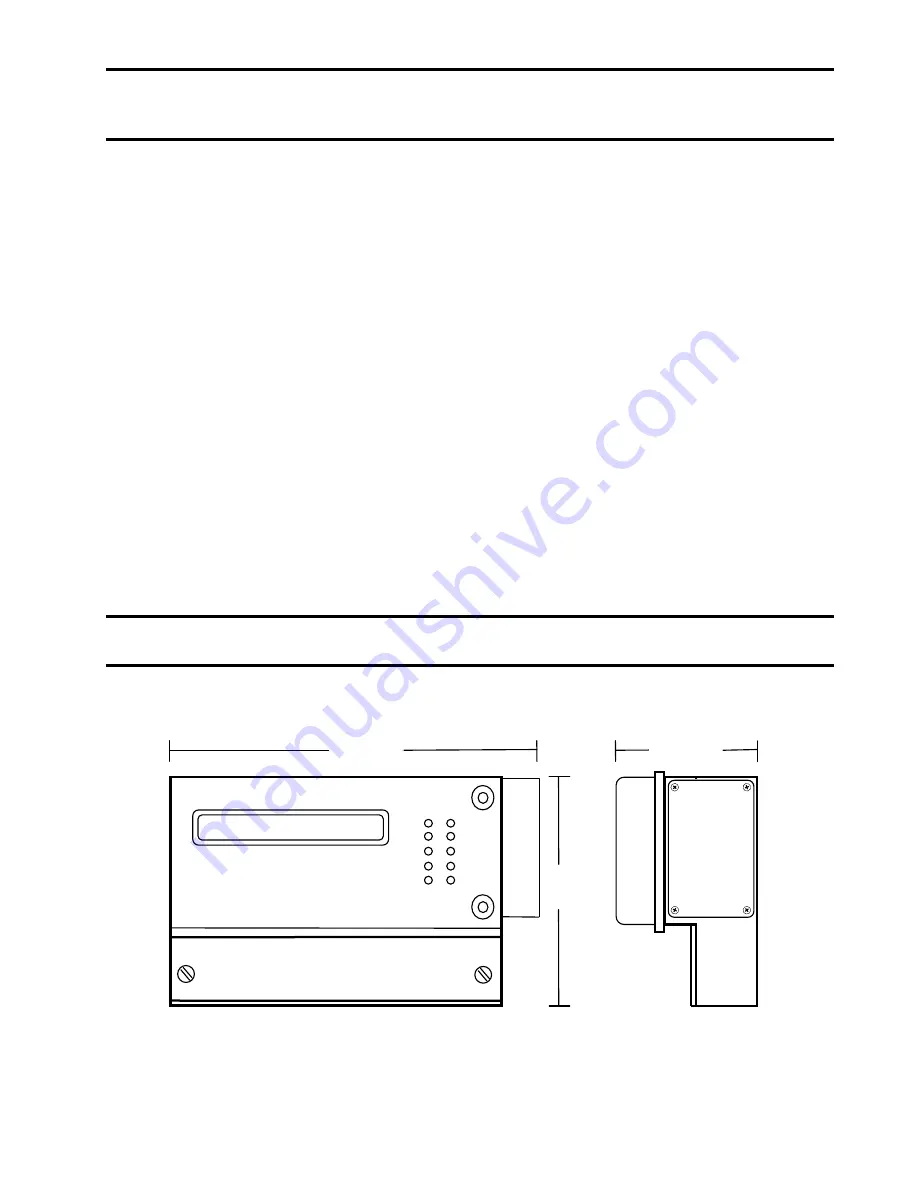
HALOGUARD
II CONTROLLER
4
1/4
”
Figure 1 - Dimensional Drawing


