background image

Rev.1/26/98


10


CALIBRATION 

Haloguard IR monitors are factory calibrated to the gas of interest; field recalibration is not required for 

operation in typical machine room environments during the first twelve months of operation unless drift 

exceeds more than 5ppm in a 30 day period. 

For those who wish to check the factory calibration an optional Digital Calibrator and Span Gas Kit is 

available. Instructions for use are included with kit


TESTING 


The Haloguard IR

TM

 should be tested at start-up, after any changes to alarm protocol, and after each alarm 

level condition has been corrected.


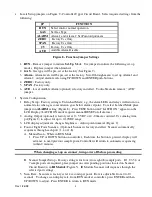
During Testing, display will indicate TEST MODE 

a.  Alarm Test - Push TEST button five times to check all alarm levels sequentially.  Alarm relays, 

lights, audible and remote alarms (if equipped) will activate. 

b.  Reset Test - Push RESET/SILENCE button; alarm relays, audible and remote alarms (if equipped) 

will become inactive for 20 minutes.  Display will read  RESET  and indicate minutes to completion 

of reset period. 


TROUBLESHOOTING 


The most frequent cause of nuisance alarms and faults is improper set-up, primarily due to: 

      a.    Failure to install in accordance with instructions. 

b.  Not allowing sufficient warm-up time. 

c.  Poor sensor location. 


To check Zero Calibration, fill a clean plastic trash bag with clean outside air, tie off  with twist-tie, let 

sample stabilize inside for 15 - 20 minutes.  Insert sample tube into bag . For models equipped with scanner 

allow up to 2.5 minutes per channel for clean air sample analysis 

Observe LCD response, if dispalyed PPM value drops lower then Haloguard IR is detecting the presence of 

the gas of interest or another gas which absorbs IR light at the same frequency. 


Remove sample tube from bag and observe LCD response. If displayed PPM value moves higher, look for 

refrigerant leaks or possible sources of interfering gases  (See “Before Installation” section 3e). and relocate 

sensor. Keep in mind that the Haloguard IR is much more sensitive than hand held leak detectors, it may 

detect a leak when  hand held units  show no response 

 
We wish to aid with any  problems you might experience with the Haloguard IR

.  When contacting Thermal 

Gas Systems, Inc. Service Department, please have the following information ready 


1.  Model Number and Serial Number. 

2.  Description of problem. 

3.  Remove faceplate. Place jumper on Alarm setting function. and record settings.   

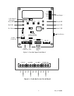
4.  Measure voltage between SIG and GND.(Fig. 2) in SETUP and RUN modes  Write down values 

5.  Advise the condition of all LED’s and all information displayed on the LCD. 


Summary of Contents for HALOGUARD Series

Page 1: ...G as Type 1 R 11 2 R 12 3 R 22 4 R 134a 5 6 7 R 123 Range 1 0 1000 ppm M ount 1 W all O utputs 11 4 x 3A Relays 12 0 5 VDC or 0 10 VDC 13 4 20mA O ptions Accessories A Audible Alarm B UPS E Inlet Outl...

Page 2: ...n 10 5 Testing 10 6 Trouble Shooting 10 7 Specifications 11 FIGURES Page 1 Dimension Drawing 4 2 Controller Upper Circuit Board 5 3 Controller Lower Circuit Board 5 4 Controller LCD Display Features 6...

Page 3: ...ase circuit rated 15A minimum Haloguard Controller and IR Sensor Module b Infrared IR Sensor Module should be mounted near potential leaks in a quiet area or downstream from leak source in area with a...

Page 4: ...d relay when installed TLV TWA Alarm is factory set and not user adjustable e OFFSCALE LED and Relay Factory set at 1000ppm f RESET Push button Silences alarm disables relays and resets instrument for...

Page 5: ...Lower Circuit Board RUN GAS ALARM ZERO SPAN AUD J5 ANALOG VOLT mA I C Offscale LED Alarm 2 LED Alarm 1 LED Power LED Fault LED Test Button IR Trim Analog Trim Pot 0 5 or 0 10 VDC UP ENTER DOWN Sensor...

Page 6: ...ailure Scan Stop Gas Type R 11 R 12 R 123 R 134 etc Figure 4 Controller LCD Display Features 8 hr TWA Concentration R 123 Concentration ppm Channels 1 8 Optional Scanner Only Flashing cursor means Aut...

Page 7: ...face plate from Haloguard Controller and IR Sensor Module using screw driver 2 Run cable from Haloguard Controller to IR Sensor Module location Eight feet 8FT of cable with DIN connectors standard op...

Page 8: ...tting Figure 8 Press TEST button until LATCH ON appears on the LCD Display LATCH ON mode requires manual RESET of all alarms 2 Analog Output optional is factory set at 0 5 VDC or 4 20mA as ordered Use...

Page 9: ...troller Terminal Provided Wire Color Extension Wire Color Function SCAN Red Red Scanner SIG White White Signal GND Blk Blk Black Ground Note SCAN Terminal is used with scanner Only Figure 6 Sensor Cab...

Page 10: ...allowing sufficient warm up time c Poor sensor location To check Zero Calibration fill a clean plastic trash bag with clean outside air tie off with twist tie let sample stabilize inside for 15 20 min...

Page 11: ...on condensing Controller 0o F to 120o F Non condensing Fault Diagnostics Indicator Light or LCD Readout for fault diagnostics See Figure 5 Materials IR Module NEMA 4 12 13 IP 65 Design Controller NEMA...

Page 12: ...OFFSCALE ALARM 2 Notes 1 Power Cord Provided w wall plug connector and 8 Ft 3 conductor wire 2 Audible and Visual Alarm Optional factory wired Remote Audible and Visual Alarms must be 120VAC and conne...

Reviews: