4
Rev.2 1/26/98
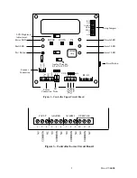
5. LED Indicators, Pushbuttons, LCD Displays, and Relays
a.
POWER LED
-
Green LED indicates Haloguard
is receiving AC power.
b.
FAULT LED and Relay
-
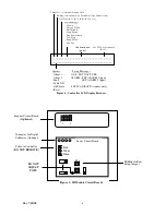
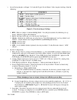
Indicates malfunction.
LCD indicates specific type of failure (See
Figure 4).
c.
TEST Push-button
-
Energizes Alarm LED’s & relays. Depress button five (5) times to
sequence through each alarm level.
d.
Adjustable Alarm LEDs & Relays
-
Indicate
Alarm 1&Alarm 2
-
Factory set for particular
refrigerant (See Figure 9). User adjustable as follows:
RANGE
1 PPM
INCREMENTS
10 PPM
INCREMENTS
0 - 1000 ppm
10 - 100
100 - 1000
Note: Optional TWA Integration activates Alarm 1 LED and relay when installed.
TLV-TWA Alarm is factory set and not user adjustable.
e.
OFFSCALE LED and Relay
- Factory set at 1000ppm
f.
RESET Push-button
-
Silences alarm, disables relays, and resets instrument for 20 minutes.
LCD displays *CAUTION* and RESET with 20 minute countdown. Alarms are
automatically reactivated if alarm condition is not corrected. Reset is automatically initiated
on start-up and after power failure (Except when optional UPS is provided.).
6. Optional Features:
. TWA Integration - Haloguard
calculates an 8 hr. Time Weighted Average (TLV-TWA)
,
displays this value on LCD, activates Alarm 1 LED and relay if factory set PPM value is
exceeded. Only used for gases with TLV-TWA less than 1000ppm.
HALOGUARD
IR
CONTROLLER
5 1/2”
Figure 1 - Dimensional Drawing
4”
9”
3/4”
HALOGUARD
IR
MODULE
6 1/2”
14 1/4”
(By 4” Deep)


