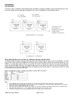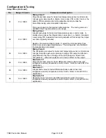
TSBC Instruction Manual
Page 20 of 48
Installation
Terminal Layout
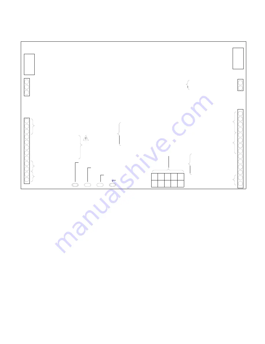
TSBC Terminal Layout Guide
Remote System Temperature
(10k ohm Thermister, 5 Vdc)
Outside Air Temperature
(10k ohm Thermister, 5 Vdc)
Domestic Hot Water Priority
Local / Remote
Remote On / Off (Enable)
Spare Input (Programmable)
12 Vdc Common
Remote Firing Rate or
Setpoint Input (0-10 Vdc)
(See Note)
Mixing Valve Output
(4-20 mAdc)
Lockout Indicator
Spare Output Start/Stop
Boiler Pump Start/Stop
System Pump Start/Stop
Spare Output (Programmable)
12Vdc Common
CA
OO
Alternate Connection For
Outside Air Temperature and
Remote System Temperature
(10k ohm Thermister, 5 Vdc)
Call For Heat Output
Low Water Cutoff Switch Input
Boiler Outlet Temperature
(10k ohm Thermister, 5 Vdc) Common
Boiler Inlet Temperature
Boiler Peer-To-Peer
Communication
Network
V-
V+
P-
P+
GP
WF
HL
Power Common (-24 Vac)
Power Supply (+24 Vac)
Flame Safeguard Alarm
(24 Vac)
Fuel Valve Energized
(24 Vac)
P-, P+ - Firing Rate Demand (0-10 Vdc, PWM)
V-, V+ - Firing Rate Demand (0-10 Vdc)
OO - Burner On/Off Switch
WF - Low Water Flow Switch
GP - Gas Pressure Switch
HL - Operating or High Limit
CA - Low Combustion Air Flow
Thermal Solutions Boiler Control
™
(TSBC
™
)
TERMINAL LAYOUT GUIDE
RJ-45
(8 pin)
O+
O-
O-
R+
R+
R-
R-
DP
O+
LR
RO
SI
C
C
C
SP
BP
VI
LO
C-
C+
MR
MS
SO
C
C
BC
BO
BI
CH
LC
C
PR
AL
CS
RJ-11
(6 pin)
12 Vdc,
0.5 A max total
for LO, VI, BP,
SP and SO
24
Vac
12
Vdc
Label 101175-04
24
Vac
WARNING:
All connections have different inputs and ouputs.
Refer to connections on diagrams for individual inputs/outputs.
(Terminal connections as viewed from front of boiler)
NOTE:
Valid signal range for terminals C+ and C- is 1-9VDC.
See boiler wiring diagram for details.


