background image


41 


8.5 Set-Up Changing Function 

Some functions or settings, such as, temperature differential, filter reminder, louver position memory, 
auto-restart, anti-code air can be changed or disabled with the remote control according to different 
requests.  

Important:

  The function can only be accessed in 30 seconds when the batteries were installed in the 

remote control, and the indoor unit must be turned off.  


8.5.1   Set-up Steps 

Follow the steps below to enter the set-up changing manual. 


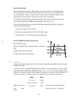
Press  and  hold  the  three  buttons  "MODE",  "FAN"  and  "TIMER 
ON"  simultaneously  for  5  seconds  within  30  seconds  after  the 
batteries were installed in the remote control.  


Press "TEMP UP/DOWN" button to select the setup code. 


Press "MODE" button to enter the setup range.  


Press "FAN" or "TIMER OFF" to select the setup range. 


Press "TIMER ON" to confirm and exit. 


8.5.1   Set-up Manual 

Note:

 All temperature here is in Celsius. 


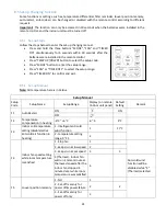
Setup Manual 

Setup 
Code 

Setup Name 

Setup Range 

Display (on remote 
/indoor unit panel) 

Default 

Setting 

Remark 

F1 

Auto Restart 

ON 


ON 


OFF 


F2 

Temperature 
compensation in heating  

-6°C ~ +6°C 

-6 ~ 6 

4°C 


F3 

Indoor coil temperature 
setting (disable/active 
anti-cold air function in 
heating) 

1 - Intelligent anti cold 
wind function 

17°C 


2 - temperature setting 
range: 0~21 


F4 

Indoor fan speed setting 
while room temperature 
is satisfied 

1 - Stop fan 


2 - keeps run at low speed  2 


3 - keeps run at set speed  3 


4 (Thermal) - indoor fan 
will run 1 more minute at 
the lowest speed after the 
indoor fan stopped 4 
minutes later while room 
temperature was satisfied. 


Anti-cold wind 
function will be 
disabled while "4" 
(Thermal) selected 

F5 

Louver position memory 

1 - NO 


2 - Set-off memory for 
power off & power failure 

3 - Set-off memory for 
power off only 


Summary of Contents for 12H47YIMI

Page 1: ...7 22 2021 SINGLE ZONE MINISPLIT SERVICE MANUAL For the following models 9H47YIMI 9H47YOMI 12H47YIMI 12H47YOMI 12H47ZIMI 12H47ZOMI 18H47ZIMI 18H47ZOMI 24H46ZIMI 24H46ZOMI 30H48ZIMI 30H48ZOMI 36H46ZIMI...

Page 2: ...iring Diagram 17 5 1 Indoor Unit 17 5 2 Outdoor Unit 18 6 Installation Details 22 6 1 Wrench Torque Sheet 22 6 2 Cable Connection Sheet 22 6 3 Pipe Size Length and Elevation 22 6 4 First Time Installa...

Page 3: ...Set up Steps 41 8 5 1 Set up Manual 41 9 Troubleshooting 43 9 1 Indoor Unit Error Codes 44 9 2 Diagnosis and Solution 45 9 2 1 E0 F4 EEPROM Parameter Error 45 9 2 2 E1 Indoor Outdoor Communication Err...

Page 4: ...N 69 9 3 6 Pressure on Service Port 70 10 Unit Disassembly 72 10 1 Indoor Unit 72 10 1 1 Accessing the Terminal Block 72 10 1 2 Removing the Front Cover Housing 73 10 1 3 Removing the Indoor PCB 75 10...

Page 5: ...ed circuit breaker Use this appliance on a dedicated circuit For electrical work contact the dealer seller a qualified electrician or an authorized service center Always ground the product Install the...

Page 6: ...pecial purposes such as preserving foods works of art etc It is a consumer air conditioner not a precision refrigeration system Do not block the inlet or outlet of air flow Use a soft cloth to clean D...

Page 7: ...C Rated Voltage Y 115V Z 230V D Type of unit I Indoor unit O Outdoor unit X Internal Code Indoor Outdoor Voltage V Capacity BTU Heat Pump 9H47YIMI 9H47YOMI 115 9 000 X 12H47YIMI 12H47YOMI 12 000 X 12...

Page 8: ...ul gases and odors Follow Me With this feature a temperature sensor is built into the remote control The unit will use that temperature sensor for the ambient temperature so the air conditioner is fol...

Page 9: ...l easily dissolves in refrigerant especially in low temperature conditions The crankcase heating belt can heat the bottom of the compressor to avoid pumping out too much oil with the refrigerant which...

Page 10: ...10 1080 mm 226 mm 335 mm 30H48ZIMI 49 57 1259 mm 11 1 282 mm 14 25 362 mm 36H46ZIMI...

Page 11: ...1 7 Right rear wall hole 2 5 Indoor Unit Outline 28 43 9K 31 57 12K 1 7 1 7 1 1 7 Left rear wall hole 2 5 8 6 22 87 1 3 2 37 99 18K 42 52 24K 2 1 1 8 5 3 2 1 1 8 5 5 85 5 95 6 86 Indoor Unit Outline R...

Page 12: ...above is for reference only The appearance of actual units may be different Model W D H W1 A B 9H47YOMI 30 31 770 mm 11 81 300 mm 21 85 555 mm 32 40 823 mm 20 87 530 mm 11 42 290 mm 12H47YOMI 12H47ZO...

Page 13: ...4 1 Refrigerant Cycle Diagram For models 9H47YOMI 12H47YOMI 12H47ZOMI 18H47ZOMI 24H46ZOMI LIQUID SIDE GAS SIDE HEAT EXCHANGE EVAPORATOR HEAT EXCHANGE CONDENSER COMPRESSOR 2 WAY VALVE 3 WAY VALVE 4 WAY...

Page 14: ...VAPORATOR HEAT EXCHANGE CONDENSER Compressor 2 WAY VALVE 3 WAY VALVE 4 WAY VALVE COOLING HEATING T2 Evaporator temp sensor T1 Room temp sensor T3 Condenser temp sensor T5 Discharge temp sensor T4 Ambi...

Page 15: ...city BTU Outdoor Temoerature F 12K 80F 17052 18900 18000 15243 0 5000 10000 15000 20000 75F 85F 95F 105F Capacity BTU Outdoor Temoerature F 18K 80F 22540 24485 24000 20152 0 5000 10000 15000 20000 250...

Page 16: ...2547 10116 7685 4425 0 2000 4000 6000 8000 10000 12000 14000 16000 18000 20000 57F 47F 37F 17F 5F 5F 13F Capacity BTU Outdoor Temoerature F 18K 55F 70F 28547 26521 22022 17523 13688 9852 5623 27412 25...

Page 17: ...17 5 Wiring Diagram 5 1 Indoor Unit For models 9H47YIMI 12H47YIMI 12H47ZIMI 18H47ZIMI 24H46ZIMI For models 30H48ZIMI 36H46ZIMI...

Page 18: ...18 5 2 Outdoor Unit Model Voltage V Capacity BTU Type 9H47YOMI 115 9 000 HEAT PUMP 12H47YOMI 115 12 000 HEAT PUMP...

Page 19: ...19 Model Voltage V Capacity BTU Type 12H47ZOMI 230 12 000 HEAT PUMP...

Page 20: ...20 Model Voltage V Capacity BTU Type 18H47ZOMI 230 18 000 HEAT PUMP 24H46ZOMI 230 24 000 HEAT PUMP...

Page 21: ...21 Model Voltage V Capacity BTU Type 30H48ZIMI 230 30 000 HEAT PUMP 36H46ZIMI 230 36 000 HEAT PUMP...

Page 22: ...unit Please refer to the nameplate before selecting the cable fuse and disconnect box The supply power cable should be selected according to the specifications sheet shown below Appliance Amps AWG Wi...

Page 23: ...m 6 4 1 Gas Leak Check Soap Water Method Apply soap water or a neutral liquid detergent to the indoor unit line set connections and service ports with a soft brush If bubbles start forming there is a...

Page 24: ...en retighten the flare nut Make sure the pressure display in the pressure indicator is 10 psi higher than the atmosphere pressure Then remove the charge hose from the 3 way valve 8 Fully open the 2 wa...

Page 25: ...lays the proper weight refer to the gauge and the pressure of the low side disconnect the charge hose from the 3 way valve s service port immediately and turn off the air conditioner before disconnect...

Page 26: ...he charge hose Open the Handle Lo valve of the manifold valve slightly to purge air from the charge hose for 5 seconds and then close it quickly 4 Set the 2 way valve to the close position 5 Operate t...

Page 27: ...ect the vacuum pump to 3 way valve s service port 3 Evacuation for approximately two hours Confirm that the compound meter indicates 500 microns mHg 4 Close the valve low side on the charge set turn o...

Page 28: ...on the charge set and charge the system with liquid refrigerant If the system cannot be charged with the specified amount of refrigerant or can be charged with a little at a time approximately 5oz or...

Page 29: ...y should be less than 80 If the air conditioner operates beyond this figure the surface of the air conditioner may attract condensation Please set the vertical air flow louver to its maximum angle ver...

Page 30: ...ed or Timer OFF is activated This code illuminates when unit is defrosting This code illuminates when anti cold air function is turned on This code illuminates when unit is in self cleaning process Th...

Page 31: ...because the refrigerant system was designed to operate at a specific safety pressure If the pressure gets too high the compressor may get overload and an explosion may even occur in extreme circumsta...

Page 32: ...ctivated the compressor will run with low frequency When the current is more than setting value the current protection function will be activated and the compressor will stop 8 4 2 2 Outdoor Fan Logic...

Page 33: ...or temperature protection The compressor will stop when the evaporator temperature below the setting value 8 4 3 Heating Mode 8 4 3 1 Compressor Operation Logic When T1 Ts T the compressor will stop w...

Page 34: ...the compressor is on the indoor fan can be set to high med low auto And the anti cold wind function has the priority The indoor fan is controlled as below Setting fan speed Actual fan speed H H H G A...

Page 35: ...for 15 minutes in defrosting mode 8 4 3 5 Evaporator temperature protection Off Compressor stops Decrease Decrease the running frequency to the lower level Hold Keep the current frequency Resume No li...

Page 36: ...he same as normal auto mode with 75 F setting temperature When AC receives signals from the remote control such as switch on switch off timer on timer off mode setting fan speed setting sleeping mode...

Page 37: ...hutting down its louver will restore to the angle originally set by the user but the precondition is that the angle must be within the allowable range if it exceeds it will memorize the maximum angle...

Page 38: ...hen the Silence function is activated the compressor running frequency will keep in low and the indoor unit will bring faint breeze which will reduce the noise to the lowest level and create a quiet a...

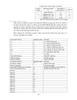
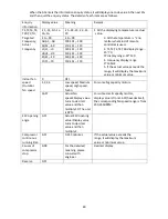
Page 39: ...ween 5 9 6 5 3 6 2 Between 6 6 7 8 7 2 3 Between 7 9 8 5 10 8 4 Note See Setup Manual on page 37 for changing Enquiry information Displaying code Meaning T1 T T1 Room temperature T2 T T2 Indoor coil t...

Page 40: ...19 99 A0 A1 A9 100 101 109 b0 b1 b9 110 111 119 c0 c1 c9 120 121 129 d0 d1 d9 130 131 139 E0 E1 E9 140 141 149 F0 F1 F9 150 151 159 Indoor fan speed Outdoor fan speed 0 OFF 1 2 3 4 Low speed Medium sp...

Page 41: ...OFF to select the setup range Press TIMER ON to confirm and exit 8 5 1 Set up Manual Note All temperature here is in Celsius Setup Manual Setup Code Setup Name Setup Range Display on remote indoor un...

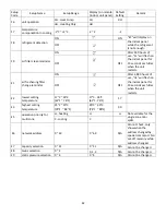
Page 42: ...reminder ON After 2 880 hours of use nF will flash on the indoor panel for 15 seconds each time when the unit restarts OFF OFF E2 lowest setting temperature 17 C 24 C 62 F 76 F 17 C 24 C 62 F 76 F 17...

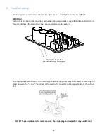
Page 43: ...Do not forget to discharge the electricity in the capacitors before troubleshooting Electrolytic Capacitors CAUTION HIGH VOLTAGE For other models please connect the discharge resistance approximately...

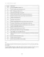
Page 44: ...r discharge temperature sensor T5 open circuit or short circuit F4 Outdoor unit EEPROM parameter error F5 Outdoor fan speed has been out of control P0 IPM malfunction or IGBT over strong current prote...

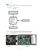
Page 45: ...eplace the main PCB directly Otherwise check whether the EEPROM chip plugged in main PCB well Yes No Yes Correct the connection Replace the main PCB Shut off the power supply and turn it on 5 seconds...

Page 46: ...later No Replace the outdoor main PCB Power on Is the error extinguished Replace the outdoor main PCB Power on Is the error extinguished Check the outdoor wiring connection Check the outdoor wiring co...

Page 47: ...the voltage will move alternately between 25V to 25V If the outdoor unit is faulty the voltage will move alternately with positive value If the indoor unit is faulty the voltage will be a specific val...

Page 48: ...edback for four 4 minutes or the zero crossing signal time interval is abnormal Possible Causes Wiring mistake PCB faulty Check if the connections and power supply is normal Correct the connections Tu...

Page 49: ...PCB faulty Power off then restart the unit 2 minutes later Shut off the power supply Rotate the fan by hand The unit operates normally Find out the cause and have it solved Check the wiring of fan mot...

Page 50: ...2 3 Black GND 0V 4 White Vcc 14 17 5V 5 Yellow Vsp 0 5 6V 6 Blue FG 14 17 5V 2 Outdoor DC Fan Motor control chip is in outdoor PCB Power on and check if the fan can run normally if the fan can run no...

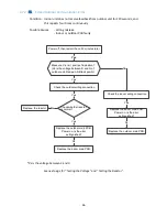
Page 51: ...ible Causes Wiring mistake Sensor faulty Check the connection between temperature sensor and PCB Correct the connection No Yes Replace indoor or outdoor main PCB Measure the resistance value of the se...

Page 52: ...artup During the first five 5 minutes of starting up if T2 TC 3 8 F 2 C does not hold for four 4 continuous seconds three 3 times Possible Causes T2 sensor faulty Indoor PCB faulty Refrigerant system...

Page 53: ...ent Protection Condition An abnormal current rise is detected by checking the specified current detection circuit Possible Causes Wiring mistake Power supply problems System blockage Compressor malfun...

Page 54: ...in PCB and compressor Correct the connection or replace the wires and connectors Yes No Check the IPM No Yes Replace the IPM board or replace the main PCB Check the outdoor fan and the outdoor unit ve...

Page 55: ...55 Note The pictures below are only for reference they may be not same as the ones on your unit P U P V...

Page 56: ...56 P W N U...

Page 57: ...57 N V N W...

Page 58: ...he resistance between every two ports of U V W of IPM and P N If any result of them is 0 or close to 0 the IPM is defective and has to be replaced Otherwise please follow the procedure below Refer to...

Page 59: ...B faulty Check the power supply Check the connections and wires Stop the unit No Yes No Correct the connections or replace the wires Yes Replace the reactor Yes No Replace the IPM board Check the volt...

Page 60: ...r up the air inlet and outlet or the heat exchanger of indoor and outdoor units Yes No Yes Yes Power off then restart the unit 10 minutes later Check if the temperature of compressor No Check refriger...

Page 61: ...tection voltage detection compressor rotation speed signal detection etc Possible Causes Wiring mistake IPM malfunction Outdoor fan assembly faulty Compressor malfunction Outdoor PCB faulty For 9K to...

Page 62: ...ery two ports of U V W of IPM and P N first If any result of them is 0 or close to 0 the IPM is defective and has to be replaced Otherwise please follow the procedure below Refer to Section 9 3 5 Plea...

Page 63: ...value the pressure protector will switch off After the pressure resume to normal the protection code will extinguish Possible Causes Wiring mistake Pressure protector faulty Outdoor fan assembly fault...

Page 64: ...e value of each winding by using the multimeter Position Resistance 68 F 20 C 9H47YOMI ASN98D22UFZ 12H47YOMI ASN98D22UFZ 12H47ZOMI ASN98D22UFZ 18H47ZOMI ASM135D23UFZ 24H46ZOMI ATF235D22UMT 30H48ZOMI A...

Page 65: ...the resistance using a multimeter The variables for the different temperature sensors are shown below T1 Room temperature sensor T2 Indoor coil temperature sensor T3 Outdoor coil temperature sensor T4...

Page 66: ...38991 2 28 39 8239 38 100 5 62961 78 172 1 25423 118 244 0 37956 1 30 37 1988 39 102 5 39689 79 174 1 2133 119 246 0 36954 0 32 35 2024 40 104 5 17519 80 176 1 17393 120 248 0 35982 1 34 33 3269 41 10...

Page 67: ...34 93 37 3 72 162 8 94 110 230 2 781 3 27 211 4 35 95 35 78 73 163 8 643 111 232 2 704 2 28 200 7 36 97 34 32 74 165 8 358 112 234 2 63 1 30 190 5 37 99 32 94 75 167 8 084 113 235 2 559 0 32 180 9 38...

Page 68: ...table below for proper resistance values Position Resistance Red Black Several M P N U V W U N V W Red 9 3 4 Outdoor AC Fan Motor Check To check if the outdoor fan motor is working properly measure t...

Page 69: ...mal Voltage on P and N 208 240VAC 1 phase 3 phase 380 420VAC 3 phase Standby Around 310 VDC Around 530 VDC Operating With passive PFC module With partial active PFC module With fully active PFC module...

Page 70: ...ODT IDT 75 23 89 85 29 44 95 35 105 40 56 115 46 11 PSI 70 59 119 113 117 125 147 PSI 75 63 124 120 126 132 155 PSI 80 67 135 129 132 140 162 F C ODT IDT 75 23 89 85 29 44 95 35 105 40 56 115 46 11 MP...

Page 71: ...37 33 2 78 0 56 27 23 2 78 5 17 13 8 33 10 56 PSI 55 439 413 367 330 302 PSI 65 471 435 386 368 339 PSI 75 489 457 403 381 362 F C ODT IDT 57 53 13 89 11 67 47 43 8 33 6 11 37 33 2 78 0 56 27 23 2 78...

Page 72: ...units The model used for the demonstration down below is the 24H45YZIMI 24H45ZOMI 10 1 Indoor Unit 10 1 1 Accessing the Terminal Block Follow the following steps to gain access to the terminal block...

Page 73: ...ottom of the unit under the front cover Number of screws will depend on model 2 Remove the screws located under the front flip up cover Additional screws maybe hidden under the horizontal louver cover...

Page 74: ...ving the front cover housing be aware there is a wire connecting the cover housing and the indoor PCB Be sure to disconnect this connector 5 When the front cover housing is removed the unit can be pro...

Page 75: ...the Indoor PCB First follow the steps to remove the front cover housing from the previous section then follow the steps below to remove the indoor PCB 1 First remove the screw holding the cover on th...

Page 76: ...ok the clip 3 Lift the cover up from the bottom and pull out to remove cover The picture on the right shows what the electronics box looks like with the cover removed NOTE The connections shown below...

Page 77: ...the top of the terminal block 7 Disconnect the transformer primary connector 8 Disconnect the CN3 evaporator coil sensor 9 Disconnect the CN1 ambient temperature sensor 10 Disconnect the indoor fan m...

Page 78: ...cted to gain access to other connectors that need to be disconnected 1 Remove the screw for the ground wire in the location shown above 2 Remove the screw on the bottom of the electronics box See pict...

Page 79: ...Unit 10 2 1 Removing the Outdoor PCB 1 Remove the nine 9 screws on the top lid of the condenser unit 2 Lift and remove the lid from the top of the unit 3 Remove the two screws on the side panel of th...

Page 80: ...80 4 There are hooks on the side edges of the side panel First push down on the panel to unhook it and then pull it forward to remove Picture of outdoor unit with side panel removed...

Page 81: ...Remove the wires from the clips holding them in place 6 There are four tabs that hold the plastic of the PCB in place Use a flathead screwdriver or some kind of wedging tool if necessary to unhook the...

Page 82: ...82 7 Then lift the PCB assembly off the unit NOTE All wires are still connected...

Reviews: