VH8000 Series
Beyond the past, Exceed the present, Surpass the competition
E
n
g
lis
h
E
n
g
lis
h
10
9
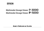
Finish PSU installation.
Fasten the supporting bridge using
screws.
2.8 Accessory Storage
The top sliding hood allows easy access to the extra
storage space for small tools and accessories.
Press to remove the accessory storage if necessary.
3.1 Motherboard Installation
Chapter3 Motherboard & Leads Installation
Each motherboard has different standoff layout. It is highly suggested that you refer to your
motherboard's manual when installing motherboard into the Case. Armor+ MX is applicable
with ATX & Micro ATX motherboards. Your motherboard may require a special I/O Panel,
which should be included with your motherboard.
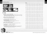
Placement Direction:
When installing the motherboard, make sure you follow the direction provided by your motherboard
manufacturer. On most standard motherboards, the edge with external ports goes to the rear part
of the chassis. It is highly recommended that you install CPU, heat sink and modular components
before fixing the motherboard inside the chassis.
= the locations of
the screw holes. Note
these locations and
place included
standoffs on the chassis
first.
This side towards
the rear of the
chassis
Above illustration is a sample of what
the motherboard's layout. For more
detail screw hole placement, please
refer to your motherboard manual.
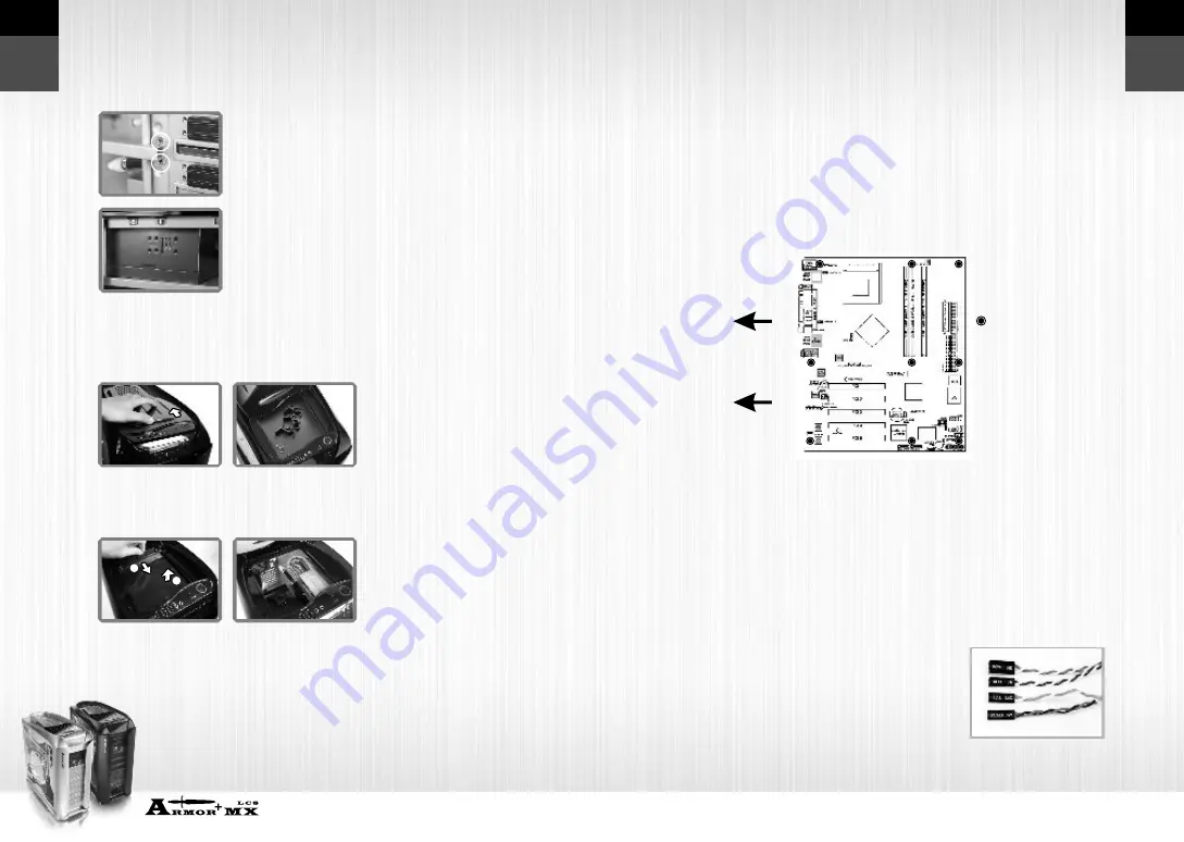
3.2 Case LED connection
On the front of the case, you can find some LEDs and switch leads (POWER SW*1, POWER LED*1,
H.D.D. LED*1, RESET SW*1) Please consult user manual of your motherboard manufacturer, then
connect these leads to the panel header on the motherboard. Theseleads are usually labeled; if not,
please trace them back to the case front to find out their source.
-
POWER LED
connects to your M/B at the PLED
-
POWER SW
connects to the PWR connector on the motherboard
-
H.D.D LED
connects to the 2-pin labeled HDD LED connector
-
RESET SW
connects to the RSW connector on the motherboard
1
2