background image

VH8000 Series

Beyond the past, Exceed the present, Surpass the competition

E

n

g

lis

h

E

n

g

lis

h

18

17

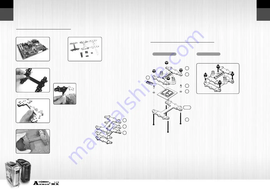
4.4.1  Intel LGA 775 - Secure Waterblock onto CPU

Intel LGA 775 
Motherboard

Components for
LGA 775:

Tear off the tape on the 
back of the insulator (C) 
and place it on the metal 
H-type clip(A).

Combine the insulator(C) and 
the cushion (B) using the 
adhesive. Stick the metal H-type 
clip(A) with the insulators (BC). 
Tear off the protective layer to 
adhere it onto the motherboard.

Attach H-type clips(including 
ABC)on the back side of 
motherboard.

Note: Placing the cushion onto 
the motherboard with the 
adhesive will prevent you from 
removing the cushion in the 
future. If you are planning to 
remove the cushion for future 
use, please don't remove the 
protective tape.

A-Metal H-type clip 
B-Cushion
C-Insulator
D-50mm screws
E-Thumb nuts 
G-Thermal 
     compound
I  -Stand offs
J  -Red washers

Install the Clip on Motherboard 

4.4  Install Waterblock 

Install Waterblock  on Motherboard 

 Exploded View

Completed View

1.Insert the screws (D) through the clip(ABC)
   into the four holes on the  Motherboard.
2.Put the washers (J) along the screws to prevent
   the electric current.
3.Put the stand offs (I) along the screws to fix the 
   screws on the motherboard.
4.Apply a thin layer of thermal compound(G) onto 
   the processor.
5.Place waterblock on the processor through the 
   screws and fix it by thumb nuts(E). 


A

B

C

A

B

C

D

E

G

I

J

A

C

B

G

A C

B

E

A

I

J

D

Summary of Contents for Armor+ MX LCS VH8000 Series

Page 1: ...f liability Thermaltake s responsibility under this or any other warranty implied or expressed are limited to repair or replacement as set forth above These remedies are the sole and exclusive remedies for any breach of warranty Thermaltake is not responsible for direct special incidental or consequential damages resulting from any breach of warranty or under any other legal theory including but n...

Page 2: ...CS Module 1 4 Liquid Cooling System Dual 5 25 Drive Bay design Pre built liquid cooling system Quick Disconnect Connector Automatic non spill valves robust material one hand operation 120mm Motorsports Radiator A Dimple Tube Technology with louvered fin radiator B Silent 120mm variable resistor fan spinning from 1300 2400RPM High performance Liquid Pump Powerful DC 12V liquid pump 500L hr Pure Cop...

Page 3: ...rive bay metal cover Install the 5 25 drive bay cover as shown Pull the right hand side of the lever to remove the 5 25 device 1 2 1 2 How to remove 5 25 device How to put back the 5 25 drive bay cover 2 3 3 5 Device Installation Unlock the tool free clip Insert the 3 5 drive into the front of chassis Secure the 3 5 device as shown Remove the 3 5 plastic cover 2 4 HDD Installation Remove the HDD t...

Page 4: ... tray Slide the HDD tray back to the drive bay 2 6 PCI Slot Tool Free Usage Take off the PCI bracket Locate Graphic Card to the motherboard through fixing it on the space of PCI bracket and insert it to the PCI slot Notice Fix the pin into the hole Push back the plastic clip to secure the Graphic Card 2 7 Power Supply Installation Release the plastic clip as shown Unscrew the PSU supporting bridge...

Page 5: ...s the edge with external ports goes to the rear part of the chassis It is highly recommended that you install CPU heat sink and modular components before fixing the motherboard inside the chassis the locations of the screw holes Note these locations and place included standoffs on the chassis first This side towards the rear of the chassis Above illustration is a sample of what the motherboard s l...

Page 6: ...ive Signal for Port 4 BLACK GROUND USB Ground KEY VCC USB Power 5C for Port 3 D USB Negative Signal for Port 3 D USB Positive Signal for Port 3 GROUND USB Ground RED WHITE GREEN BLACK NC 3 4 Audio Connection Please refer to the following illustration of Audio connector and your motherboard user manual Please select the motherboard which used AC 97 or HD Audio Azalia be aware of that your audio sup...

Page 7: ...Dimensions Bearing Maximum Capacity Rated Voltage Input current Connector Noise Life time Weight Dimension Major Material Ingredient Capacity Material Dimension Weight Application Tubing Hoes Clip Dimension Material Fan Connector Noise Fan Speed Fan Dimension Tubing Hoes Clip Fin Design Tube Design Material Dimension 130 2 L x 107 2 W x 51 5 H mm 330 c c 75 L x 70 W x 75 H mm Ceramic bearing 500 L...

Page 8: ...nuts x4 F White washers x4 G Thermal compound H 38mm screws x4 I Stand offs x4 J Red washers x4 Installation Complete Components Check P 15 Install Waterblock Intel LGA775 Intel P4 478 AMD K8 AMD AM2 AM2 P 17 Install Water tube P 27 Fill Coolant 12cm Radiator Main Unit P 30 P 29 Clips for Intel LGA 775 P4 478 AMD AM2 AM2 K8 P Screws for radiator x 4 K 6mm Screws for PCI bracket x 2 L PCI bracket M...

Page 9: ...event you from removing the cushion in the future If you are planning to remove the cushion for future use please don t remove the protective tape A Metal H type clip B Cushion C Insulator D 50mm screws E Thumb nuts G Thermal compound I Stand offs J Red washers Install the Clip on Motherboard 4 4 Install Waterblock Install Waterblock on Motherboard Exploded View Completed View 1 Insert the screws ...

Page 10: ...View 1 Insert the screws D through the clip ABC into the four holes on the Motherboard 2 Put the washers J along the screws to prevent the electric current 3 Put the stand offs I along the screws to fix the screws on the motherboard 4 Apply a thin layer of thermal compound G onto the processor 5 Place waterblock on the processor through the screws and fix it by thumb nuts E Completed View A Metal ...

Page 11: ...ushion in the future If you are planning to remove the cushion for future use please don t remove the protective tape A B C D E F G Check The Back Plate Install Waterblock on Motherboard 4 4 3 AMD K8 Socket 754 939 940 Secure Waterblock onto CPU A Standard installation Install waterblock by motherboard back plate AMD K8 Motherboard Components for AMD K8 G Thermal compound H 38mm screws Remove the ...

Page 12: ...ayer of thermal compound G onto the processor 5 Place waterblock on the processor through the screws and fix it by thumb nuts E 21 4 4 4 AMD Socket AM2 AM2 Secure Waterblock onto CPU AMD AM2 Motherboard Components for AMD AM2 AM2 G Thermal compound H 38mm screws Remove the retention frame from motherboard Install Waterblock on Motherboard Check The Back Plate Check Your Back Plate A Standard insta...

Page 13: ...hion in the future If you are planning to remove the cushion for future use please don t remove the protective tape Install Waterblock on Motherboard Combine the insulator C and the cushion B using the adhesive Stick the metal H type clip A with the insulators BC Tear off the protective layer to adhere it onto the motherboard Attach H type clips including ABC on the back side of motherboard Explod...

Page 14: ...alling water tube please install motherboard to the case first Then remove black rubber caps from the waterblock Insert the hose clip N through the tube In Out CPU Waterblock Pump and Liquid Tank Radiator A B C Connect Main Unit to Waterblock Step Connect Waterblock to Radiator Insert the hose clip and female quickconn connector through the tube Use pliers to tighten the hose clip N A Step B Inser...

Page 15: ...he motherboard s fan connector Pre built main unit in 5 25 drive bay Connect the 4 pin connector of pump to power supply 4 7 Fill Coolant Open the top sliding hood of the chassis and remove the accessory storage Fill the tank up with coolant Turn on the PC power switch Liquid level will decrease when you power on the system please keep filling coolant until the tank is filled up Close the cover of...

Page 16: ... ensure optimal cooling performance Pump Water Tank Radiator Ensure pump is working proper Check for water level within the water tank we strongly recommend checking the water level once a month If the liquid level is below the low level please follow the installation steps on manual to refill the coolant Note It is recommended that coolant to be replace once every 6 months Depending on the worklo...

Page 17: ...truction when un installing Please refer to installation and reverse the procedures Q Can I add another liquid cooling upgrade kits on my liquid cooling system A Yes there are numerous upgrades available for all different components in PC Please visit www thermaltake com for more information Q How do I know if the pump is working A Place your hand on the pump If the pump is operating the pump shou...

Reviews: