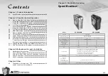
background image

VH6000 Series

17/18

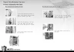
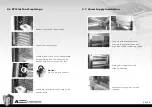
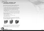
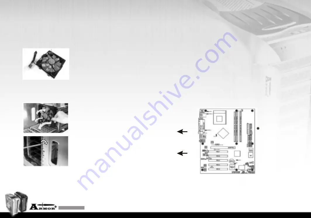
3.1  Motherboard Installation

Chapter3  Motherboard & Leads Installation

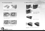
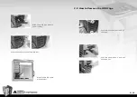
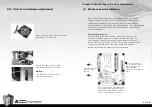
2.11  VGA Fan Installation (Optional)

Each motherboard has different standoff layout.  It is highly 

suggested that you refer to your motherboard's manual when 

+

installing motherboard into the Case.  Armor  is applicable 

with Extend ATX, ATX & Micro ATX motherboards. Your motherboard

may require a special I/O Panel, which should be included with

your motherboard.

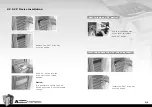
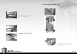
Placement Direction:

When installing the motherboard, make sure you follow the 

direction provided by your motherboard manufacturer.  On 

most standard motherboards, the edge with external ports 

goes to the rear part of the chassis.  It is highly recommended 

that you install CPU, heat sink and modular components 

before fixing the motherboard inside the chassis.
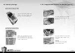
    = the locations of 
the screw holes.  Note 
these locations and 
place included 
standoffs on the chassis 
first.

This side towards 
the rear of the 
chassis

Above illustration is a sample of what 
the motherboard's layout. For more 
detail screw hole placement, please 
refer to your motherboard manual.

Install 140mm fan to the fan holder 

provided in the tool box.

Secure the fan holder to the 

motherboard tray by screws.

Notice:


The direction of fan airflow 

should be as shown. 

Summary of Contents for Armor VH6000 Series

Page 1: ...Co Ltd All Rights Reserved 2007 10 C Tested To Comply With FCC Standards FOR HOME OR OFFICE USE All other registered trademarks belong to their respective companies www thermaltake com Beyond the pass Exceed the present Surpass the competition ...

Page 2: ... series optional 4 1 02 03 03 04 05 06 06 07 08 10 11 12 14 15 15 15 16 17 18 19 20 22 22 23 Specification Chapter 1 Product Introduction Model Case Type Dimension W D H Side panel Material Color Cooling System Motherboards Drive Bays Front I O Expansion Slots VH6000SWA Super Tower Transparent window Front door Aluminum Chassis 1 0mm SECC All Aluminum Front intake 140 x 140 x 25mm blue LED fan 100...

Page 3: ...l lock is opened Push down the thumb screw to open the side panel Open the transparent side panel Pull up the thumb screw to open the side panel Open the right hand side panel To remove the transparent side panel please remove upper and bottom thumb screws on the back of the case To remove the right hand side panel please remove upper and bottom thumb screws on the back of the case ...

Page 4: ... into the drive bay till the locked position How to remove 5 25 device Install the 5 25 drive bay cover as shown 1 2 Notice It is possible to secure the 5 25 device by screws if not feel stable enough Pull the right hand side of the lever to remove the 5 25 device How to put back the 5 25 drive bay cover ...

Page 5: ... the drive device into the bay and secure the tray by 5 25 slot in kit Install the 5 25 to 3 5 adaptor cover provided in the tool box to the case as shown 2 4 HDD Installation Remove the HDD tray by pressing the handle and pull the tray out Secure HDD using the clips onto the HDD tray for both side Place HDD on the tray ...

Page 6: ...2 Organized HDD cable management 2 5 How to Remove the HDD Cage Push the handle down and pull the cage out Press the handle to lock the HDD tray Slide the HDD tray back to the drive bay Unscrew the thumb screws of the cage ...

Page 7: ...porting bridge Place power supply over the location as shown Fasten power supply by screws included Release the plastic clip as shown Take off the PCI bracket Locate Graphic Card to the motherboard through fixing it on the space of PCI bracket and insert it to the PCI slot Push back the plastic clip to secure the Graphic Card Notice Fix the pin into the hole ...

Page 8: ...to the appropriate position Fasten both side of PSU supporting bridge using the thumb screws 2 8 Sliding Motherboard Tray Remove the screws from the back of the chassis Slide the motherboard tray towards the back of the case to remove it from the case ...

Page 9: ...e provided tool box Then put the storage draw into the drive bay till the locked position Top accessory storage Storage draw optional 2 10 Swappable HDD Module Fan Module Optional Lay down your case and unscrew the thumbscrews to remove the HDD cage Notice The direction of fan airflow should be as shown Put a fan and secure it by screws and thumb nuts provided in the tool box ...

Page 10: ...n provided by your motherboard manufacturer On most standard motherboards the edge with external ports goes to the rear part of the chassis It is highly recommended that you install CPU heat sink and modular components before fixing the motherboard inside the chassis the locations of the screw holes Note these locations and place included standoffs on the chassis first This side towards the rear o...

Page 11: ...connects to the PWR connector on the motherboard H D D LED connects to the 2 pin labeled HDD LED connector RESET SW connects to the RSW connector on the motherboard 3 2 Case LED connection 3 3 USB 2 0 IEEE 1394 Firewire Connection USB connection Please consult your motherboard manual to find out the section of USB connection VCC USB Power 5C for Port 4 RED WHITE D USB Negative Signal for Port 4 GR...

Page 12: ...e check with your motherboard manual before installing PRESENCE BLACK SENSE1_RETURN AUD GND SENSE2_RETURN YELLOW BROWN RED PORT1 R PORT2 R PORT1 L BLUE PORT2 L SENSE_SEND KEY PURPLE GREEN AUDIO AZALIA Function ORANGE BLACK GROUND Front Audio Ground L RET Rear Left Channel Audio Signal Rear Right Channel Audio Signal R RET NC BROWN RED MIC IN MIC POWER Front Microphone Power Front Microphone input ...

Page 13: ...loading on current PSU and no need to upgrade current PSU while running multi graphic cards mode The functions can assure all Thermaltake Power Supply meets the balance in noise control and heat exhausted All power supply provides complete protection function as follow 1 Over power protection 2 Short circuit protection on all output 3 Over voltage protection Under voltage protection 4 Over current...

Page 14: ...VH6000 Series 25 26 ...

Reviews: