background image

11

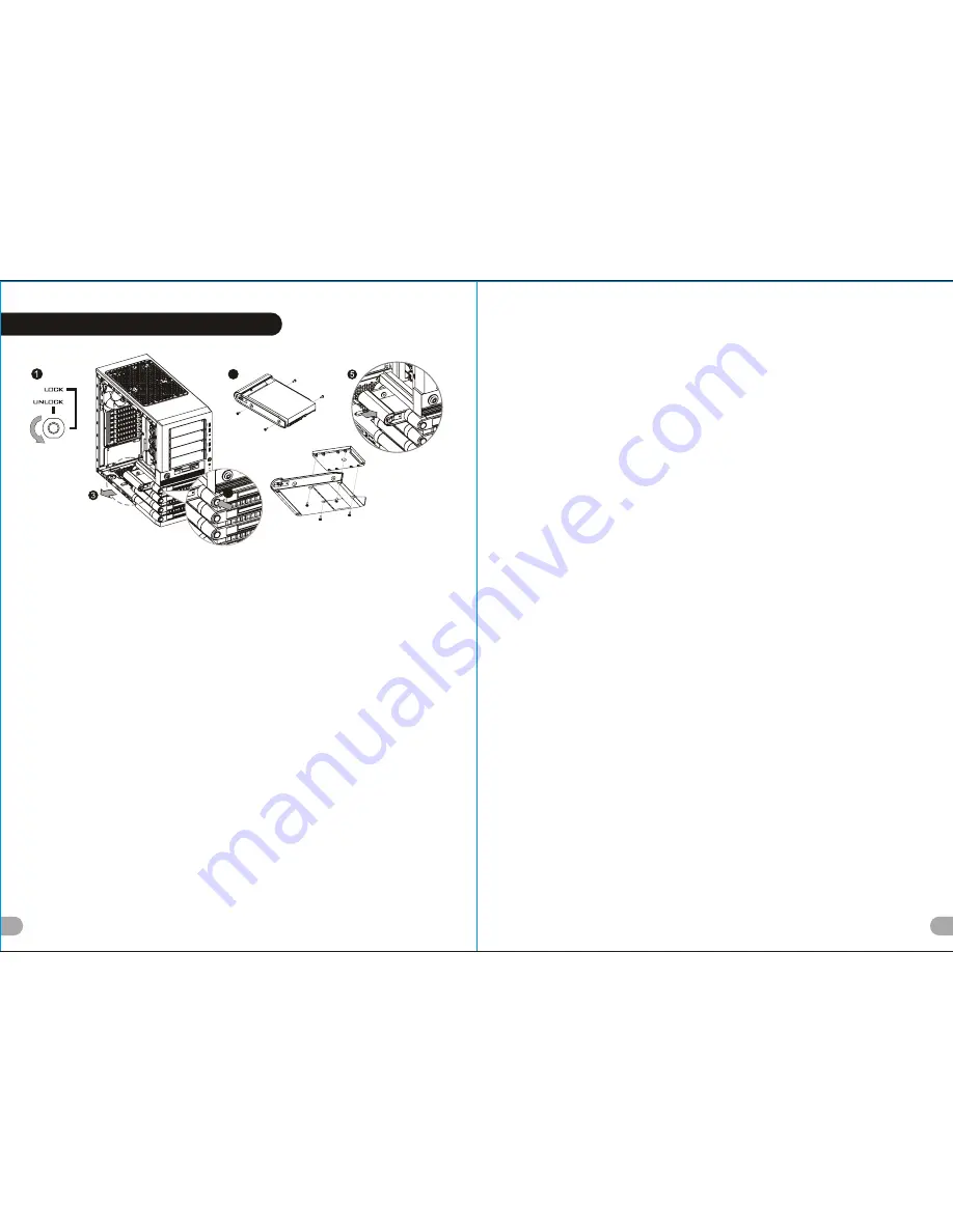
3.5  & 2.5  HDD Installation

12

English /

1. 

Turn the keyhole of the front panel into the OPEN 

position using the key.

2. Push and hold the release button on the front panel.

3. Pull the HDD tray out. 

4. Place the 2.5  or 3.5  hard drive on the tray and 

secure it with screws.

5. Slide the HDD tray back to the HDD cage. 

Deutsch /

1. Drehen Sie das Schloss der Frontverkleidung mithilfe 

des Schlüssels in die Position OFFEN

2. Drücken und halten Sie den Entriegelungsknopf auf 

der Frontverkleidung.

3. Ziehen Sie den HD-Schacht heraus.

4. Montieren Sie die 2,5 oder 3,5 Zoll Festplatte im 

Schacht und sichern Sie sie mit Schrauben.

5. Schieben Sie den Schacht wieder in den 

Festplattenkäfig.

Français /

1. Tournez le trou de la serrure du panneau avant dans 

la position OUVERTE en utilisant la clé.

2. Appuyez sur le bouton de libération sur le panneau 

avant et maintenez-le enfoncé.

3. Enlevez le boîtier du disque dur.

4. Placez le disque dur de 2,5  ou de 3,5  dans le 

boîtier et fixez-le avec des vis.

5. Refaites glisser le boîtier du disque dur dans la 

cage de disques durs.

Español /

1. 

Gire el ojo de la cerradura del panel frontal a la 

posición OPEN (ABIERTO) utilizando la llave.

2. Empuje y sostenga el botón de liberación del panel 

frontal.

3. Extraiga la bandeja del disco duro.

4. Coloque el disco duro de 2 5 ó 3'5  en la bandeja y 

fíjelo con los tornillos.

5. Vuelva a meter la bandeja del disco duro en su 

hueco.

Italiano /

1. 

Ruotare il foro del pannello anteriore in posizione 

OPEN (APERTO) utilizzando la chiave.

2. Tenere premuto il pulsante di rilascio sul panello 

anteriore.

3. Estrarre il vano HDD.

4. Posizionare il disco fisso da 2,5  o 3,5  nel vano e 

fissarlo con le viti.

5. Fare scorrere l HDD indietro verso la struttura a 

gabbia HDD.

Português /

1.

Rode o orifício do painel dianteiro para a posição 

OPEN (aberto), com a chave.

2.

Mantenha premido o botão para abrir no painel 

dianteiro.

3. Puxe a bandeja do disco rígido para fora.

4. Coloque o disco rígido de 2,5  ou 3,5  na bandeja e 

fixe com parafusos.

5. Deslize a bandeja do disco rígido de volta para a 

caixa do disco rígido.

4

3.5" HDD

2.5" HDD

 /

1. 


 OPEN (


.

2. 


.

3. 


 HDD.

4. 

   2,5 "  3,5" 


.

5. 

   HDD 


 HDD

 /

1.

OPEN

2.

3. 

4.  2 .5 3 .5

5. 

 /

1. 

OPEN

2. 

3. 

4.  2 .5 3 .5

5. 

 /

1. 

OPEN

2. 

3.

HDD

4. . 5

HDD SSD 

  .

5

HDD

5. 

HDD

HDD

 /

1. 


OPEN (

).

2. 


.

3. 


.

4. 

 2,5- 

 3,5-


.

5. 


.

Türkçe /

1. Ö

n panelin anahtar deli ini, anahtar


kullanarak AÇIK 

konumuna getirin.

2. Ön paneldeki serbest b rakma dü mesini bas l


tutun.

3. HDD tepsisini d

ar  çekin.

4. 2,5  veya 3,5  sabit disk sürücüsünü tepsinin 

üzerine yerle tirin ve vidalarla sabitleyin.

5. HDD tepsisini HDD kafesine geri yerle tirin.

 /

1. 


OPEN (

)

2. 

3. 

 HDD 

4. 

 2.5  

 3.5  

5. 

 HDD 

 HDD

V O 30 0 0 S e rie s

Le v el 10 GTS

12/0

1

/02

A

32

80

4

157G

P

X

2

(g/m )

MARKETING

CHECK

DESIGN

PRODUCT GM

2

(g/m )

)

Poki

125

 mm

176

 mm

Summary of Contents for GTS VO3000 Series

Page 1: ...л чит т нич ю н льт цию гл т чн Б з вы дны www sotmarket ru д бн я инф м ция т в тзывы бз ы и ы Инструкция Level 10 GTS VO30001N2N Thermaltake Перейти в карточку товара 8 800 775 98 98 ...

Page 2: ...www thermaltake com User s Manual Benutzerhandbuch Mode d emploi Manual del usuario Manuale dell utente Manual do Utilizador kullan c elkitab EEE Yönetmeli ine Uygundur Tested To Comply With FCC Standards FOR HOME OR OFFICE USE VO3000 Series B o r n t o b e f r e e 12 01 02 A 4 157G P X MARKETING CHECK DES PRODUCT GM 2 g m Po 125 mm ...

Page 3: ...16dBA Top exhaust optional 200 x 200 x 30 mm fan x 1 or 120 x 120 x 25 mm fan x 2 Side intake optional 200 x 200 x 30 mm fan or 140 x 140 x 25 mm fan x 1 Bottom Intake optional 120 x 120 x 25 mm USB 3 0 x 2 USB 2 0 x 2 HD Audio x 1 Supports 1 2 3 8 1 4 water tube 4 x 5 25 1 x 3 5 1 x 3 5 or 2 5 4 x 3 5 or 2 5 Side Panel Disassembly Motherboard Installation PSU Installation 5 25 Device Installation...

Page 4: ...calor de la CPU es de 175 mm 6 9 pulgadas Límite de longitud para la tarjeta gráfica VGA El límite de longitud para la tarjeta gráfica VGA en de 315 mm 12 4 pulgadas Attenzione Limite di altezza per il dissipatore di calore della CPU Il limite di altezza per il dissipatore di calore della CPU è 175 mm 6 9 Limite di lunghezza per la VGA schede grafiche Il limite di lunghezza per la VGA scheda grafi...

Page 5: ...nglish 1 Lay down the chassis 2 Install the motherboard in proper location and secure it with screws Deutsch 1 Legen Sie das Gehäuse auf die Seite 2 Installieren Sie die Hauptplatine in ihrer vorgesehenen Position und sichern Sie sie mit Schrauben Français 1 Posez à plat le châssis 2 Installez la carte mère dans l endroit approprié et sécurisez la avec des vis Español 1 Tumbe el chasis 2 Instale l...

Page 6: ...ie die passenden Öffnungen Bringen Sie die Verriegelungseinheit wieder an und drehen Sie sie gegen den Uhrzeigersinn um das Laufwerk zu sperren Français 1 Retirez le couvercle de la baie de lecteur 5 25 2 Tournez le verrou dans le sens des aiguilles d une montre pour déverrouiller et retirez le verrou 3 Mettez le périphérique 5 25 dans la baie de lecteur 4 Cherchez les ouvertures adéquates Remette...

Page 7: ...rksschacht ein 3 Führen Sie die 3 5 Zoll HDD ein und befestigen Sie sie mit den Schrauben Français 1 Retirez le couvercle de la baie de lecteur 3 5 2 Insérez le périphérique 3 5 dans la baie pour lecteur 3 Insérez le disque dur de 3 5 et sécurisez le avec les vis Español 1 Extraiga la cubierta de la bahía de unidad de 3 5 pulgadas 2 Coloque el dispositivo de 3 5 pulgadas en la bahía de unidad 3 In...

Page 8: ...l frontal 3 Extraiga la bandeja del disco duro 4 Coloque el disco duro de 2 5 ó 3 5 en la bandeja y fíjelo con los tornillos 5 Vuelva a meter la bandeja del disco duro en su hueco Italiano 1 Ruotare il foro del pannello anteriore in posizione OPEN APERTO utilizzando la chiave 2 Tenere premuto il pulsante di rilascio sul panello anteriore 3 Estrarre il vano HDD 4 Posizionare il disco fisso da 2 5 o...

Page 9: ...Faq aspx ID 1143 Pour un système qui exécute Windows Vista http www thermaltakeusa com Faq aspx ID 1079 Pour un système qui exécute Windows XP http www thermaltakeusa com Faq aspx ID 1073 Español La ranura de intercambio sencillo se aloja para facilitar la transferencia ultra rápida hasta 3 0 Gbps de muchos datos a un disco duro SATA sin tener que utilizar una cubierta de almacenamiento externa Pa...

Page 10: ... depolama kasas kullanma zorunlulu u olmadan bir SATA sabit diskine ultra h zl aktar m n en fazla 3 0 Gb s sa lamak için yerle ik olarak tasarlanm t r Sorunsuz çal ma için lütfen a a daki ayarlar n do rulu undan emin olun 1 Ana kart n z veya SATA denetleyici kart n z için gerekli tüm sürücülerin yüklü oldu undan emin olun 2 HDD tepsisini d ar çekmek için s k n 3 3 5 HDD bile enini ürünle birlikte ...

Page 11: ...s cabos do teclado ou do rato através do Bloqueio de Segurança do Teclado e Rato e fixe na parte traseira do painel no interior do chassis com parafusos Place the keyboard or mouse cables through the Keyboard Mouse Security Lock then secure it back to the back panel from inside of the chassis with screw Führen Sie die Kabel durch die Einheit Tastatur Maussperren und sichern Sie sie dann wieder an ...

Page 12: ... 97 or HD Audio Azalia or it will damage your device s Anschlüsse herstellen Gehäuse LED Verbindungen Auf der Gehäusevorderseite finden Sie einige LEDs und Verbindungen Bitte nehmen Sie die Gebrauchsanweisung Ihres Motherboard Herstellers zur Hilfe und schließen Sie diese Verbindungen an die Panel Header Belegung des Motherboards an USB 2 0 Anschluss Bitte nehmen Sie die Gebrauchsanweisung Ihres M...

Page 13: ... L BLUE PORT2 L SENSE_SEND KEY PURPLE GREEN ORANGE BLACK AUDIO AZALIA Function Guida di installazione dei contatti Connessione del LED del case Nella parte anteriore del case sono presenti alcuni contatti per interruttori e LED Consultare il manuale utente del produttore della scheda madre quindi connettere i contatti alla parte superiore del pannello sulla scheda madre Connessione USB 2 0 Consult...

Page 14: ...NSE_SEND KEY PURPLE GREEN ORANGE BLACK AUDIO AZALIA Function LED USB 2 0 LED USB 2 0 USB USB 3 0 1 USB 3 0 2 USB 3 0 USB 3 0 AC 97 HD Azalia AC 97 HD Azalia LED LED USB 2 0 USB 3 0 LED POWER Switch USB 2 0 USB USB 3 0 1 USB 3 0 2 USB 3 0 USB3 0 AC 97 HD Azalia LED AUDIO AC 97 Function GROUND L RET R RET NC BROWN RED MIC IN MIC POWER KEY BLUE NC BLUE L OUT YELLOW R OUT BLACK YELLOW PRESENCE BLACK S...

Page 15: ...Lütfen AC 97 veya HD Audio Azalia spesifikasyonunu kullanan bir anakart seçin ses sisteminizin AC 97 veya HD Audio Azalia spesifikasyonunu destekledi ini unutmay n aksi takdirde ayg t lar n z zarar görür Kasa k ba lant s AUDIO AC 97 Function GROUND L RET R RET NC BROWN RED MIC IN MIC POWER KEY BLUE NC BLUE L OUT YELLOW R OUT BLACK YELLOW PRESENCE BLACK SENSE1_RETURN AUD GND SENSE2_RETURN YELLOW BR...

Page 16: ...n all output 3 Over voltage protection Under voltage protection 4 Over current protection 5 Over temperature protection Besides Thermaltake enables the quality assurance of all power supply 100 Hi POT and ATE Function Test 100 Burn In and AC Input cycled on off under high temperature condition Furthermore it has been approved by UL CUL TUV CB FCC CE GOST and BSMI The Thermaltake Power Supply serie...

Page 17: ...Note 12 01 02 A 4 157G P X MARKETING CHECK DES PRODUCT GM 2 g m Po 125 mm ...

Page 18: ...л т з з любым д бным б м гл т чн я л жб дд ж и Д т в з з в в ии ф мл ни дит нл н з 2 мин ты м нии Д т в и л т вин и тзывы ции и ид и Level 10 GTS VO30001N2N Thermaltake Описание Характеристики Отзывы ...

Reviews: