background image

User's Manual

 C   2003 Thermaltake Technology  Co.,Ltd. All Rights  Reserved.       REV. A   2004.08

All other registered trademarks belong to their respective companies.

P/N:A2259

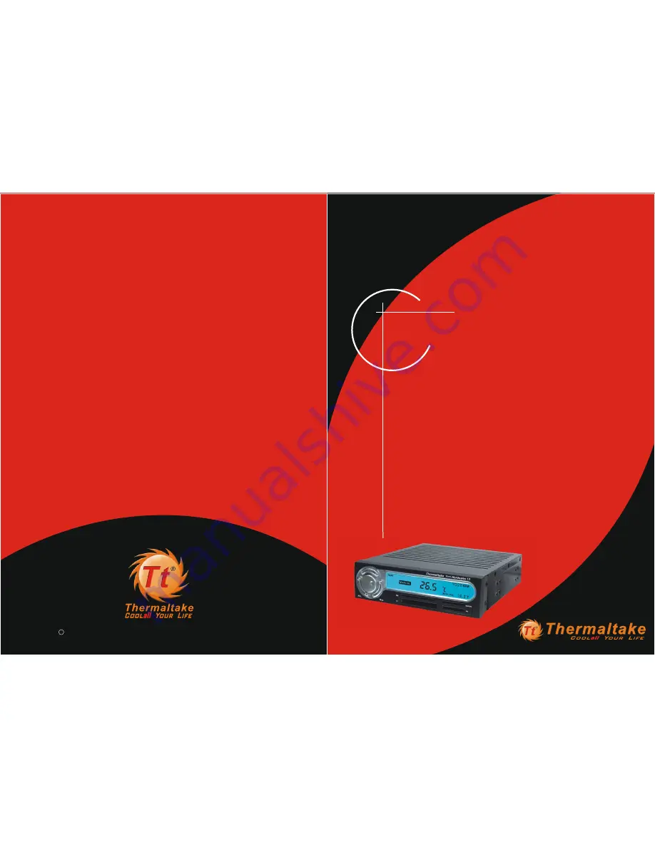
HARDCANO 13

Integrate the Intelligent Fan controller and 6 in 1 Card reader 

Multi-function  5.25 " Drive bay 

Summary of Contents for HARDCANO 13

Page 1: ...echnology Co Ltd All Rights Reserved REV A 2004 08 All other registered trademarks belong to their respective companies P N A2259 HARDCANO 13 Integrate the Intelligent Fan controller and 6 in 1 Card reader Multi function 5 25 Drive bay ...

Page 2: ...n Fan 2 4 How to Connect with 4pin Fan 2 5 What is the jumper cap for 2 6 Where should I place the Thermal sensor Probe 3 1 System Requirements 3 2 Driver Installation for Windows 98 SE and Windows 2000 3 3 Hardware setup 3 4 Drive Installation for Mac OS 8 6 3 5 Drive Installation for Mac OS 10 X 4 1 How to change A M 4 2 How to distinguish Auto Manual Mode 4 3 How to set Fan Speed only in manual...

Page 3: ... Card Reader The Intelligent Thermal Management System monitors fan speeds temperatures at 4 different locations in real time with Thermal Alarm The smart card reader supports 6 popular Flash Memory Card formats TM TM TM CompactFlash Microdrive Memory Stick TM TM TM Memory Stick Pro Secure Digital MultiMedia Card TM and SmartMedia No matter what you can be sure that your Data will be transferred t...

Page 4: ...Clock 1 Switch to Clock Mode Display in 24 Hours 2 Press 4 seconds to Time setting Mode Fan Switch the different channels circularly Fan1 Fan2 Fan3 Fan4 A M To switch between Auto Mode and Manual Mode Default Auto 1 At Manual mode adjust the fan speed by rotating the knob Rotate clockwise for acceleration counter clockwise for deceleration 2 At Time setting Mode rotate the knob to adjust the hour ...

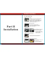
Page 5: ...B connectors STEP 5 Install The Card Reader To Motherboard Connect the 3 pin connector of the fan directly to the 3 pin socket of Hardcano 13 If the cable length is not long enough use the 3pin extension adapter Some fan units uses 4 pin connector instead of 3 pin connector In this case please use the 4pin to 3 pin adapter provided in the package to connect it to the 3pin socket of Hardcano 13 Par...

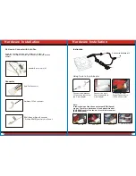
Page 6: ... be connected to 3pin fan connector 2 3 How to Connect with 3pin Fan Connectors 4pin connector X1 Connectors thermal probe X4 For power supply For VGA cooler For CPU cooler For power supply For case environment Example Example Example Example Example Example Example Example For VGA fan For CPU fan For power supply fan For case fan Connectors 3pin connector X4 Fan Control Connector 12V 5V 4pin Powe...

Page 7: ... to 4 pin X 1 Some fan unit may be using 4pin connector In order for Hardcano 13 module to control you ll need to utilize this included adaptor 4pin Fan Connector RPM Speed Signal Connector Provide RPM Signal Only Not Power Hardware Installation Hardware Installation Hardcano 13 Fan connector Connect the Hardcano 13 fan connector to the the 3 pin adapter Connect the 4 pin Power connector to 4 pin ...

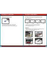
Page 8: ... Probe CPU cooler detect CPU temp VGA card cooler detect VGA temp CPU fan detect case environment temp Power supply detect PSU temp Hardcano 13 includes 4 sets of Thermal Probe Attach each Thermal Probe to different heat sources with the included thermal tape Recommended Sensor Area Hardware Installation Hardware Installation Application There are 4 sets of Thermal Sensor Probe that you may place ...

Page 9: ...nder My Computer STEP 1 Insert the driver CD into the CD ROM drive Run the program Setup exe STEP 2 The Install shield Wizard will guide you through the installation process 3 1 System Requirements One of following operating systems windows 98 SE windows 2000 Windows ME No drive needed Windows XP No drive needed Mac OS 8 6 Mac OS 9 X Mac OS X 10 1 2 No drive needed 3 2 Driver Installation for Wind...

Page 10: ...D into the CD ROM drive Run the program Setup exe STEP 2 The Install shield Wizard will guide you through the installation process While the computer is idling or it is recommended to switch operating mode to Automatic to minimize the overall noise level under minor workload While the computer is idling or under minor workload it is recommended to switch operating mode to Automatic to minimize the...

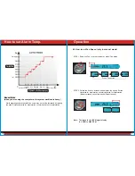
Page 11: ... different fan unit 4 3 How to set Fan Speed only in manual mode Press Fan button How to set Alarm Temp Alarm setting Temp Environment Temp 12V 6V While operating under Manual Mode users may adjust the fan speed by rotating the knob Rotate clockwise for acceleration counter clockwise for deceleration Manual Mode when you are using the computer or the system workload is heavy Note The range for the...

Page 12: ...re is shown on the LCD Default 60 O C EX This display shows Alarm temp at FAN T1 60O C 4 5 How to change the color of the LCD Panel STEP 1 Simply press Color Button as shown on the Picture Below Press 4 seconds to start the cycle of 8 color display 4 4 How to set Alarm Operation Press the Alarm button Deep Blue Yellow Red Light Blue Purple Deep Green Light Green White STEP 2 Rotate the knob to adj...

Page 13: ...he component you wish to monitor 2 Examine the Thermal Probe to see if there is any cut or Discontinuity 5 3 LCD does not display fan RPM Ans 1 Make sure the cables are connected securely 2 Verify the fan unit you are controlling monitoring has RPM signal capability Majority of the 3 wire fan have RPM signal Capability while 2 wire fans do not 5 4 LCD screen seems to be a little dimmer after some ...

Page 14: ...take Beijing Co Ltd Overseas Branch Address 525Parritott Place City of Industry CA 91746 TEL 626 968 9189 FAX 626 968 7659 E mail davidh thermaltake com USA Thermaltake Technology Inc Address 8F No 27 Lane 155 Sec 3 Pei Shen Road Saen Keng Hsiang Taipei Hsiang Taiwan TEL 886 2 2662 6501 FAX 886 2 2662 6510 E mail thermaltake thermaltake com Taiwan Thermaltake Technology Co Ltd Address No 5 A Hei A...

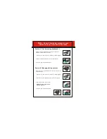
Page 15: ... A 1 Open the cover case and will see a battery on PCBA Figure D 2 Remove the battery insulation from the socket Figure B 2 Please remove the original battery from the socket Figure E 3 Cover the upper case back Figure C 3 Plug the new battery into the socket NOTE The battery model is 3volt CR2032 Figure F 4 Cover the upper case back Figure G Section 2 Changing battery process If your time memory ...

Reviews: