background image

7

8

English /

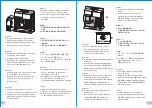
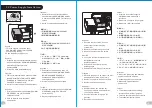
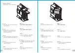
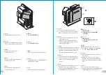
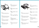
1.Turn the keyhole of the side panel PSU/

   MB/SIDE PANEL into the OPEN position 

   using the key.

2.Open the motherboard cover

.

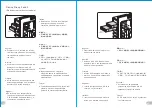
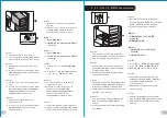
English /

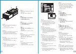
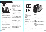
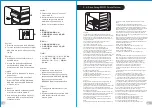
3. Unscrew the four thumbscrews from the 


motherboard tray.

Deutsch /

1. 

Drehen Sie die Schlüsselaufnahme an 

    der Seite des Gehäuses PSU/MB/SIDE 

    PANEL mithilfe des Schlüssels in die 

    Position OPEN.

2. Öffnen Sie die Hauptplatinenabdeckung.

Deutsch /

3. 

Entfernen Sie die vier Flügelschrauben 

    vom Hauptplatinenschacht.

Français /

1. 

Tournez la boutonnière du panneau 

    latéral BLOC D’ALIMENTATION/CARTE 

    MERE/PANNEAU LATERAL dans la 

    position OUVERTE à l’aide de la clé.

2. Ouvrez le couvercle de la carte mère.

Français /

3. Dévissez les quatre vis à serrage à main 

    du plateau de la carte mère.

Español /

1. 

Gire la cerradura del panel lateral PSU/MB/

    SIDE PANEL a la posición OPEN utilizando 

     la llave.

2. Abra la cubierta de la placa madre.

Español /

3. 

Desatornille los cuatro tornillos de mano 

    de la bandeja de la placa madre.

Italiano /

1. 

Ruotare l'incavo per la chiavetta del 

    pannello laterale PSU/MB/SIDE PANEL in 

    posizione OPEN (APERTO) usando la chiave.

2. Aprire la copertura della scheda madre.

Italiano /

3. 

Svitare le quattro viti ad aletta dal 

    vano della scheda madre.

繁體中文

 /

1.

用鑰匙將側板

PSU/MB/SIDE PANEL

鎖孔

   轉至

OPEN

位置.

2.

轉開主機板裝置外蓋.

繁體中文

 /

3. 

取下主機板拖盤上的四顆拇指螺絲.

日本語 /

1. 

キーを使って、側面パネルの

PSU/MB/SIDE 

    PANEL

のキー穴を「開放」位置まで回します.

2. マザーボードカバーを開けます.

日本語 /

3. 

マザーボードトレイから4本の蝶ね

    じを外します.

Русский /

1. 4. 

Поверните отверстие под ключ на 

    боковой панели 

PSU/MB/SIDE PANEL 

    (

БП/МП/БОКОВАЯ ПАНЕЛЬ) в положение 


OPEN (

ОТКРЫТО) с помощью ключа.

2. Откройте крышку материнской платы.

Русский /

3. 

Открутите четыре винта с 

    накатанной головкой из лотка для 

    материнской платы.

简体中文 /

1. 用

钥匙将侧板

PSU/MB/SIDE PANEL

锁孔转

    至

OPEN

位置.

2. 转开主机板装置外盖.

简体中文 /

3. 取下主机板拖

盘上的四颗拇指螺丝.

Türkçe


/

1. 

Anahtar

ı


kullanarak yan panelin PSU/MB/

    SIDE PANEL deli

ğ

ini OPEN (aç

ı

k) 

    konuma getirin.

2. Anakart kapa

ğ

ı

n

ı


ı

n.

Türkçe


/

3. 

Anakart tepsisindeki dört kelebek 

    viday

ı


gev

ş

etin.

1

2

2.

 Motherboard Installation

產 品 料 號

產 品 名稱

印 刷 項 目

子 件 料 號

發 稿 日 期

版 本

80

騎馬釘

4

0

書寫 紙

單色

其他 特殊 處理效 果

表面 處理

2

厚度

(g/m )

裝訂 方 式

材質

頁 數

印 刷 色彩

規 格 樣式

整 本

MARKETING

CHECK

DESIGN

PRODUCT GM

其 他 特 殊 處 理效 果

表 面 處 理

2

厚 度

(g/m )

材 質

印刷 色 彩

封面 樣 式 (當封 面 與 內 頁 樣 式 不 同 時尚 須填 寫

)

Peipei

四色

雙銅

157

g

刀模線

250 

mm

1

7

6


m

m

藍色線條為尺寸標示,請勿印刷上去!

Level 1 0 L imited E dition

manual

1 2 / 05/24

A

VL300A2N1N

Summary of Contents for Level 10

Page 1: ...ademarks belong to their respective companies www thermaltake com Tested To Comply With FCC Standards FOR HOME OR OFFICE USE User s Manual Benutzerhandbuch Mode d emploi Manual del usuario Manuale del...

Page 2: ...w 6 32 x L5 mm Screw M3 x L6 mm Screw M3 x L5mm Screw Cable Tie Key Chain Key 2 Motherboard Motherboard PSU 3 5 HDD CD ROM 2 5 HDD Cable Management Key 10 10 4 24 12 18 5 1 Q ty Used for 1 1 Specifica...

Page 3: ...PSU V rifiez que la longueur de votre carte PSU ne d passe pas 210 mm Limitaci n de altura del refrigerador de CPU Aseg rese de que la altura de su refrigerador de CPU no excede los 160 mm 6 3 pulgada...

Page 4: ...nneau lat ral du ch ssis puis faites glisser le panneau pour l ouvrir Espa ol 1 Gire la cerradura del panel lateral PSU MB SIDE PANEL a la posici n OPEN utilizando la llave 2 Gire de nuevo la cerradur...

Page 5: ...z les quatre vis serrage main du plateau de la carte m re Espa ol 1 Gire la cerradura del panel lateral PSU MB SIDE PANEL a la posici n OPEN utilizando la llave 2 Abra la cubierta de la placa madre Es...

Page 6: ...leri ve vidalar kullanarak sabitleyin 5 Anakart tepsisini tekrar i eri yerle tirin ve d rt kelebek viday s k t r n English 6 Put the motherboard cover in place 7 Turn the keyhole of the side panel PSU...

Page 7: ...kullanarak yan panelin PSU MB SIDE PANEL deli ini OPEN a k konuma getirin 2 G kayna kapa n a n English 3 Unscrew the two screws from the power supply holder using the screwdriver 4 Remove the holder a...

Page 8: ...g an 10 Drehen Sie die Schl sselaufnahme an der Seite des Geh uses PSU MB SIDE PANEL wieder mithilfe des Schl ssels in die Position LOCK Fran ais 8 Fixez fermement le bloc d alimentation 9 Replacez le...

Page 9: ...2 Aprire il coperchio del dispositivo da 5 25 e rimuoverlo 1 ODD HDD OPEN 2 5 25 5 25 1 ODD HDD 2 5 25 1 ODD HDD OPEN 2 5 25 1 ODD HDD OPEN 2 5 25 5 25 T rk e 1 Anahtar kullanarak yan panelin ODD HDD...

Page 10: ...spositivo da 5 25 nello slot e avvitare il dispositivo 4 5 25 4 5 25 4 5 25 4 5 25 T rk e 4 5 25 cihaz yuvas na yerle tirin ve cihaz s k t r n Device Group 1 Please screw it at rear screw hole English...

Page 11: ...a 5 25 usando il cacciavite quindi rimuovere i fermi 6 2 3 5 25 6 2 3 5 25 6 2 3 5 25 6 2 3 5 25 T rk e 6 Tornavida kullanarak Yuva 2 veya 3 teki vidalar 5 25 cihaz tamponlar ndan gev etin ve sonra ta...

Page 12: ...sie 10 Drehen Sie die Schl sselaufnahme der Seitentafel ODD HDD mit dem Schl ssel in die Position OPEN Fran ais 9 Replacez le panneau lat ral et verrouillez le 10 Tournez la boutonni re du panneau lat...

Page 13: ...e 11 5 25 cihaz kapa n yerine yerle tirin 12 Anahtar kullanarak PSU MB SIDE PANEL deli ini tekrar LOCK kilitli konuma getirin 12 11 English 1 Turn the keyhole of the side panel ODD HDD into the OPEN p...

Page 14: ...HDD 3 3 5 3 3 5 T rk e 3 3 5 HDD Tepsi zerine yerle tirin ve yan deliklerden vidalar kullanarak sabitleyin English 4 2 5 HDD Place it onto the tray and lock the bottom keyhole using the screws Deutsch...

Page 15: ...er dass die folgenden Einstellungen richtig sind 1 Stellen Sie sicher dass alle erforderlichen Treiber f r Ihr Mainboard oder SATA Controller Karte installiert sind 2 Dr cken um das HDD Fach herauszuz...

Page 16: ...zione formattazione di un nuovo disco rigido consultare il manuale utente del disco rigido oppure verificare il sistema in esecuzione su Windows 7 http www thermaltakeusa com Faq aspx ID 1143 Sistema...

Page 17: ...ositivo 1 PCI 2 PCI PCI 3 1 PCI 2 PCI PCI 3 1 PCI 2 PCI 3 1 PCI 2 PCI PCI 3 T rk e 1 Vidalar gev etin ve PCI tamponlar n kart n 2 PCI cihaz n PCI yuvas n n i ine yerle tirin 3 Takma i lemini tamamlama...

Page 18: ...MIC IN MIC POWER KEY BLUE NC BLUE L OUT YELLOW R OUT BLACK YELLOW PRESENCE BLACK SENSE1_RETURN AUD GND SENSE2_RETURN YELLOW BROWN RED PORT1 R PORT2 R PORT1 L BLUE PORT2 L SENSE_SEND KEY PURPLE GREEN O...

Page 19: ...compatibile con AC 97 o HD Audio Azalia in caso contrario le periferiche potrebbero venire danneggiate LED POWER Switch USB 3 0 1 USB 3 0 2 USB 3 0 USB 3 0 AC 97 HD Azalia LED LED USB 3 0 1 USB 3 0 2...

Page 20: ...table and reliable power supply becomes a necessary lesson for all PC users Why Choose Thermaltake Power Supply Quality From Within Every power supply units from Thermaltake should pass a very strict...

Reviews: