background image

4

5

English /

Deutsch /

Français /

1. 

Placez l’alimentation dans la position appropriée.

2. Ajustez le pont de support de l’alimentation dans 

la position appropriée et fixez l’alimentation à 

l’aide des vis.

Español /

1. 

Instale la PSU en la ubicación correcta.

2. Ajuste el puente de soporte de la PSU en la 

ubicación adecuada y asegúrela con tornillos.

Italiano /

1. 

Place the PSU in proper location.

2. Adjust the PSU supporting bridge to the proper 

location and secure the PSU with screws.

1. 

Platzieren Sie das Netzteil in der richtigen 

Position.

2. Richten Sie die Stützbrücke für das Netzteil 

entsprechend aus und sichern Sie das Netzteil 

mit Schrauben.

1. 

Posizionare la PSU in modo corretto.

2. Regolare il ponticello di supporto della PSU nella 

posizione corretta e fissare la PSU con delle viti.

Português/
1. Coloque o PSU na sua devida posição.
2. Ajuste a ponte de suporte do PSU para a devida 

posição e fixe o PSU com parafusos.

Power Supply Unit (PSU) Installation

繁體中文

 /

简体中文 /

日本語 /

Русский /

1. 

Установите блок питания в надлежащее место.

2. Надлежащим образом установите 

поддерживающий мост блока питания и закреп

ите блок питания винтами.

Türkçe


/

1. 將電源供應器放在正確的位置
2. 將電源供應器支撐架調整到適當的位置,然後用螺絲

固定電源供應器。

1. 

将电源供应器放在正确的位置

2. 将电源供应器支撑架调整到适当的位置,然后用螺丝

固定电源供应器。

1. 

PSU

を適切なロケーションに取り付けます。

2. 

PSU

支持ブリッジを適切なロケーションに合うよう

に調整し、ねじで

PSU

を締め付けます。

1. 

PSU’yu, uygun konuma yerle

ş

tirin.

2. PSU destek köprüsünü uygun konuma ayarlay

ı

n ve 

PSU’yu vidalarla sabitleyin.

ภาษาไทย /

1. วาง PSU ในตำแหน่งที่เหมาะสม

2. ขยับบริดจ์ที่รองรับ PSU ให้อยู่ในตำแหน่งที่เหมาะสม

    แล้วขันสกรูยึด PSU ให้แน่น

or

Type A 

Type B

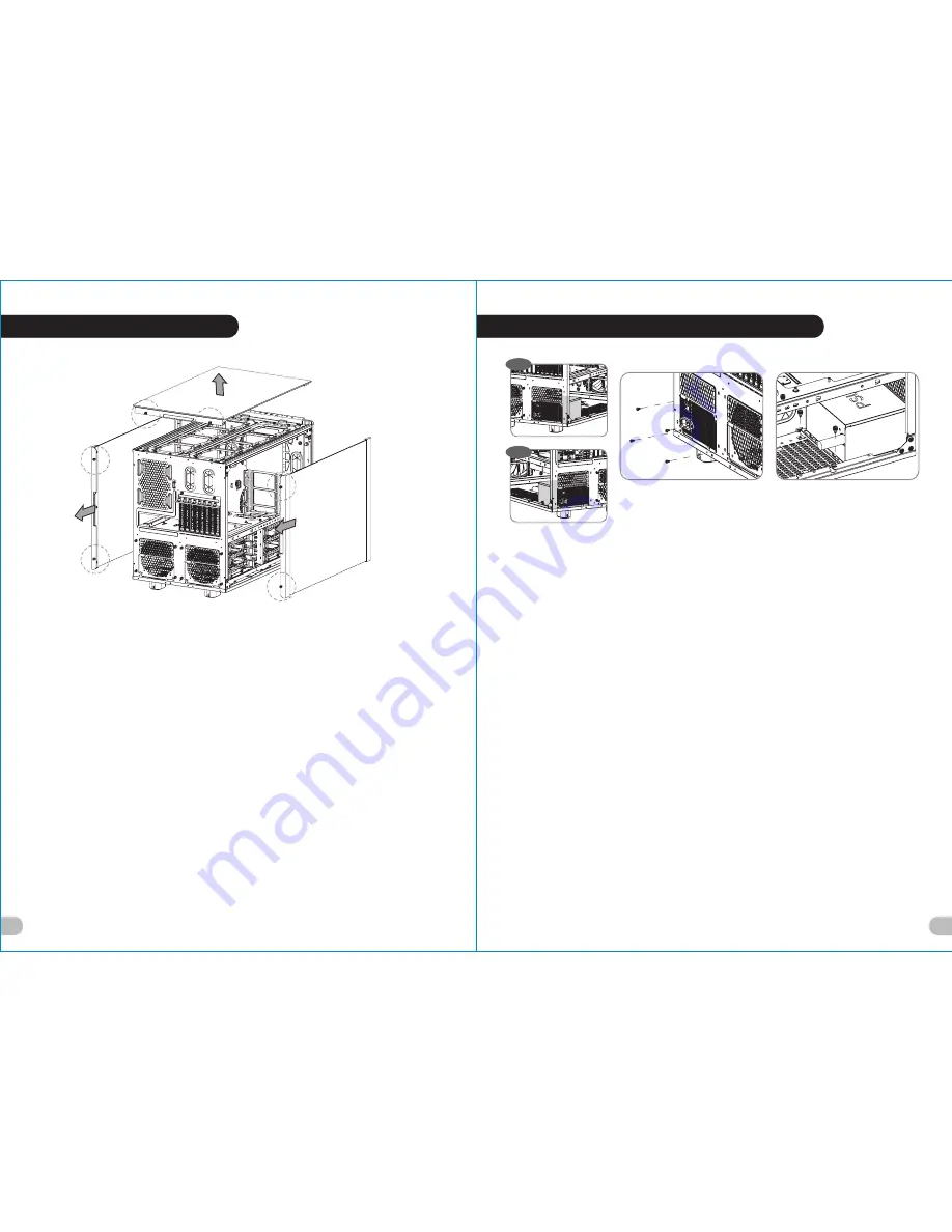
Side Panels Disassembly

English /
Remove the screws on the back of the chassis, 
and open the side panel

Deutsch /
Entfernen Sie die Schrauben auf der Rückseite 
des Gehäuses und öffnen Sie das Seitenteil

Français /
Enlevez les vis à l’arrière du châssis et ouvrez le 
panneau latéral

Español /
Extraiga los tornillos de la parte posterior de la 
caja y abra el panel lateral

Italiano /
Rimuovere le viti sulla parte posteriore dello 
chassis e aprire il pannello laterale

Português/
Remova os parafusos na parte de trás da caixa e 
abra o painel lateral

繁體中文

 /

移除機殼後方螺絲,將側窗打開

日本語 /
シャーシ背面のねじを取り外し、サイドパネ
ルを開きます

Русский /
Открутите винты на задней стенке корпуса 
и откройте боковую панель

简体中文 /
卸除机壳后方螺丝,将侧窗打开

Türkçe


/

Kasan

ı

n arkas

ı

ndaki vidalar

ı çı

kar

ı

n ve yan 

paneli aç

ı

n

ภาษาไทย /

ถอดสกรูที่ด้านหลังของแชสซีส์


แล้วเปิดแผงด้านข้าง

藍色線條為尺寸標示,請勿印刷上去!

產 品 料號

CA-1L 1-0 0F1WN-00

L evel 20 X T

說明 書

18 /0 4/ 2 6

B

產品 名稱

印刷 項目

發稿 日 期

版 本

騎馬釘

26

105

G

雙銅

單色

其他特殊處理效果

表面處理

2

厚度

(g/m )

裝訂方式

材質

頁數

印刷色彩

規格樣式

整本

CHECK

DESIGN

刀模線

125

 mm

176

 mm

Dora

(18/04/26)

Averson

(18/04/26)

Summary of Contents for Level 20 XT

Page 1: ...With FCC Standards FOR HOME OR OFFICE USE User s Manual Benutzerhandbuch Mode d emploi Manual del usuario Manuale dell utente Manual do Utilizador 安裝說明書 用戶手冊ユーザーズマニュアル Руководство пользователя kullanıcı elkitabı EEE Yönetmeliğine Uygundur คู มือการใช Picture is for reference only XT 藍色線條為尺寸標示 請勿印刷上去 18 04 26 B 發稿日期 版本 無 殊處理效果 CHECK DES 刀模 125 mm Do 18 04 Averson 18 04 26 ...

Page 2: ...h chassis have been tested to be best compatible with extreme liquid cooling configurations to ensure you get the best performance from the best features and fitment Brand official website http www thermaltake com Global Facebook https www facebook com ThermaltakeInc TT Premium To continue achieving the corporate mission of delivering the perfect user experience Thermaltake developed TT Premium wi...

Page 3: ...eft Right Side 4 x 120 mm 3 x 140 mm Bottom 3 x 120 mm Left Right Side 1 x 480 mm 1 x 420 mm Bottom 1 x 480 mm 1 x 420 mm Front 1 x 360 mm 1 x 280 mm 1x 360 mm 200 mm series Top 2 x 480 mm 2 x 420 mm 1 x 360 mm 200 mm series Rear 1 x 120 mm 1 x 140 mm Chapter 1 Product Introduction Specification Accessory Warning and Notice 1 0 1 1 1 2 01 01 02 Contents Chapter 2 Installation Guide 2 0 2 1 2 2 2 3...

Page 4: ... ดแสดงผล คือ มม 23 2 นิ ว Warning and Notice 250 mm 590 mm Warning CPU Cooler Height Limitation Please ensure that your CPU cooler does NOT exceed 250 mm 9 8 inches height VGA Add on card Length Limitation Please ensure that your VGA Add on card does NOT exceed 590 mm 23 2 inches length Warnung CPU Kühler Höhenbeschränkung Bitte stellen Sie sicher dass Ihr CPU Kühler 250 mm 9 8 Zoll Höhe nicht übe...

Page 5: ...Türkçe 1 將電源供應器放在正確的位置 2 將電源供應器支撐架調整到適當的位置 然後用螺絲 固定電源供應器 1 将电源供应器放在正确的位置 2 将电源供应器支撑架调整到适当的位置 然后用螺丝 固定电源供应器 1 PSUを適切なロケーションに取り付けます 2 PSU支持ブリッジを適切なロケーションに合うよう に調整し ねじでPSUを締め付けます 1 PSU yu uygun konuma yerleştirin 2 PSU destek köprüsünü uygun konuma ayarlayın ve PSU yu vidalarla sabitleyin ภาษาไทย 1 วาง PSU ในตำแหน งที เหมาะสม 2 ขยับบริดจ ที รองรับ PSU ให อยู ในตำแหน งที เหมาะสม แล วขันสกรูยึด PSU ให ...

Page 6: ...sition und sichern Sie sie mit Schrauben Français Installez la carte mère dans l endroit approprié et sécurisez la avec des vis Español Instale la placa madre en la ubicación adecuada y asegúrela con tornillos Italiano Installare la scheda madre nella posizione appropriata e fissarla con le viti Português Instale a motherboard no local adequado e aparafuse 繁體中文 將主機板放置在合適的位置並用零件包中之螺 絲固定 日本語 マザーボードを...

Page 7: ...винтом Inserte la tarjeta PCI en la ranura del PCI y asegúrela con tornillos PCI kartını PCI yuvasına yerleştirin ve vidayla sabitleyin Inserire la scheda PCI nello slot PCI e ภาษาไทย fissarla con la vite ใส การ ด PCI ในสล อต PCI แล วขันสกรูยึดให แน น Português Insira a placa PCI na ranhura PCI e fixe com parafusos For 2 5 HDD Secure 2 5 HDD from the bottom of the HDD by screws For 3 5 HDD Secure ...

Page 8: ...mm Rear 1 x 120 mm or 1 x 140 mm Left Right Side 1 x 480 mm or 1 x 420 mm or 1 x 480 mm or 1 x 420 mm Air Cooling Installation Top Rear Bottom Bottom Front 120 mm 120 mm 120 mm 120 mm 120 mm 120 mm 140 mm 140 mm 140 mm 140 mm 140 mm 200 mm 200 mm Front 3 x 120 mm 2 x 140 mm 2 x 200 mm Top 8 x 120 mm 6 x 140 mm 2 x 200 mm Rear 2 x 120 mm or 2 x 140 mm Left Right Side 4 x 120 mm 3 x 140 mm Side Side...

Page 9: ...12 13 Leads Installation Bracket Installation Left Side Right Side 1 2 3 3 1 2 120 mm 1 2 200 mm 藍色線條為尺寸標示 請勿印刷上去 18 04 26 B 發稿日期 版本 無 殊處理效果 CHECK DES 刀模 125 mm Do 18 04 Averson 18 04 26 ...

Page 10: ...14 15 藍色線條為尺寸標示 請勿印刷上去 18 04 26 B 發稿日期 版本 無 殊處理效果 CHECK DES 刀模 125 mm Do 18 04 Averson 18 04 26 ...

Page 11: ...17 16 藍色線條為尺寸標示 請勿印刷上去 18 04 26 B 發稿日期 版本 無 殊處理效果 CHECK DES 刀模 125 mm Do 18 04 Averson 18 04 26 ...

Page 12: ...18 19 藍色線條為尺寸標示 請勿印刷上去 18 04 26 B 發稿日期 版本 無 殊處理效果 CHECK DES 刀模 125 mm Do 18 04 Averson 18 04 26 ...

Page 13: ...藍色線條為尺寸標示 請勿印刷上去 18 04 26 B 發稿日期 版本 無 殊處理效果 CHECK DES 刀模 125 mm Do 18 04 Averson 18 04 26 20 ...

Reviews: