background image

C o n t e n t s

1

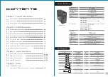
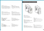
Specification

Accessory

Chapter  1.  Product  Introduction

1.1

01

Specification

1.2

01

Accessory

1.3

02

Warning and Notice

Chapter  4.   Other

Toughpower  /  TR2  / 

4.0

Lite  power  power  supply  series  (optional)

29

VN700M1W2N

VN700M1W2N 

Full Tower

535 x 220 x 580 mm

(21.1x 8.7x 22.8 inch) 

10.3 Kg / 22.7 lb

Window

Exterior & Interior : Black 

SECC

Front (intake) : 

200 x 200 x 30 mm Blue LED fan (600~800rpm, 13~15dBA)

Rear (exhaust) : 

120 x 120 x 25 mm Turbo Fan (1000rpm,16dBA)

Top (exhaust) :

200 x 200 x 30 mm Blue LED fan (600~800rpm, 13~15dBA)
200 x 200 x 30 mm fan (Optional) 

Side (intake) : Optional

200 x 200 x 30 mm fan 

Bottom (intake) : Optional

120 x 120 x 25 mm fan 

3 x 5.25’’, 1 x 3.5’’

5 x 3.5’’ or  2.5’’
1 x 3.5’’ or  2.5’’

8

9.6” x 9.6” (Micro ATX), 12” x 9.6” (ATX) , 

12” x 13” (Extend ATX) 

USB 3.0 x 2

, USB 2.0 x 2, HD Audio x 1

Standard PS2 PSU

Supports 1/2”

、3/8”、1/4” 

water tube 

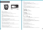
CPU cooler height limitation: 177mm
VGA length limitation: 344mm

Model
Case Type

Chassis Dimension
(H*W*D)

Net Weight

Side Panel

Color

Material

Cooling System    

Drive Bays

- Accessible
- Hidden
- HDD Docking

Expansion Slots

Motherboards

I/O Ports

PSU

LCS Upgradable

Other

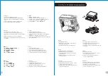
Figure

Parts  Name

Movable


Tie

M3 Screw

6#32 Hexagon Screw

6#32 Stand-off

6#32 Screw

6#32 Screw

Buzzer

8

-

pin


Extension


Cable

Q'ty

8

40

4

3

21

4

1

1

2

Used  for

Cable Management

FDD  , ODD,  2.5"HDD , Motherboard

Power

Motherboard

3.5"HDD

Top Fan

Motherboaard alarm

Power Connector Extension Cable 

Fan

Chapter  2.  Installation  Guide

2.0

04

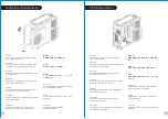
Side Panel Disassembly

2.1

05

PSU Installation

2.2

06

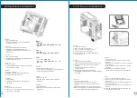
Motherboard Installation

2.3

07

5.25" Device Installation

2.4

09

External 3.5”


Device


Installation

2.5

11

3.5” & 2.5” HDD Installation

2.6

13

HDD Docking Station

2.8

20

Keyboard & Mouse Security Lock Usage

2.7

19

PCI Slot Usage

2.9

240mm Radiator Installation

21

Chapter  3.   Leads  Installation

Case  LED  Connection

3.1

22-28

USB  2.0  Connection

3.2

22-28

USB  3.0  Connection

3.3

22-28

Audio  Connection

3.4

22-28

3

pin to 4pin  adapter

Summary of Contents for Overseer RX-I

Page 1: ...panies www thermaltake com Tested To Comply With FCC Standards FOR HOME OR OFFICE USE User s Manual Benutzerhandbuch Mode d emploi Manual del usuario Manuale dell utente Manual do Utilizador Εγχειρίδιο Χρήσης 安裝說明書 用戶手冊 ユーザーズマニュアル Руководство пользователя kullanıcı elkitabı EEE Yönetmeliğine Uygundur คู มือการใช VN7000 Series ...

Page 2: ...imitation 177mm VGA length limitation 344mm Model Case Type Chassis Dimension H W D Net Weight Side Panel Color Material Cooling System Drive Bays Accessible Hidden HDD Docking Expansion Slots Motherboards I O Ports PSU LCS Upgradable Other Figure Parts Name Movable Tie M3 Screw 6 32 Hexagon Screw 6 32 Stand off 6 32 Screw 6 32 Screw Buzzer 8 pin Extension Cable Q ty 8 40 4 3 21 4 1 1 2 Used for C...

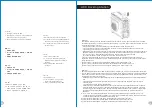
Page 3: ... installare primo dispositivo vano da 5 25 Atenção Limite de altura para o dissipador do CPU O limite de altura para o dissipador do CPU é 177 mm 7 polegadas Limite de comprimento para VGA placa gráfica O limite de comprimento para VGA placa gráfica é 344 mm 13 6 polegadas Se estiver a instalar uma ventoinha na parte frontal superior da caixa não instale o dispositivo da primeira baía de 5 25 Προε...

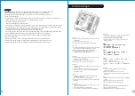
Page 4: ...n arkasındaki vidaları çıkarın ve yan paneli açın ภาษาไทย ถอดสกรูที ด านหลังของแชสซีส แล วเปิดแผงด านข าง English Place the power supply in proper location and secure it with screws Deutsch Installieren Sie das Netzteil an seiner Position und sichern Sie es mit Schrauben Français Mettez l alimentation dans le bon endroit et sécurisez la avec des vis Español Coloque el suministro de alimentación en...

Page 5: ...t panel 2 Remove the 5 25 drive bay cover 3 Remove the 5 25 drive bay metal cover 4 Place 5 25 device into the drive bay Note Press the 5 25 tool free mechanism to unlock the device Deutsch 1 Ziehen Sie das Frontpanel heraus 2 Entfernen Sie die Abdeckung des 5 25 Zoll Schachts 3 Entfernen Sie die Metallabdeckung des 5 25 Zoll Schachts 4 Platzieren Sie die 5 25 Zoll Einheit in den Laufwerkschacht A...

Page 6: ...mak için 5 25 araçsız mekanizmayı bastırın ภาษาไทย 1 ถอดแผงด านหน าออก 2 ถอดฝาปิดช องไดรฟ ขนาด 5 25 ออก 3 ถอดฝาปิดโลหะของช องไดรฟ ขนาด 5 25 ออก 4 ใส อุปกรณ ขนาด 5 25 เข าในช องไดร ฟ หมายเหตุ กดตัวล อคเครื องมือขนาด 5 25 เพื อปลดล อคอุปกรณ English 1 Pull out the front panel 2 Remove the 3 5 drive bay cover 3 Remove the 3 5 drive bay metal cover 4 Insert the device into the 3 5 drive bay 5 Insert th...

Page 7: ...ด านหน าออก 2 ถอดฝาปิดช องไดรฟ ขนาด 3 5 ออก 3 ถอดฝาปิดโลหะของช องไดรฟ ขนาด 3 5 ออก 4 ใส อุปกรณ เข าในช องไดร ฟขนาด 3 5 5 ใส HDD ขนาด 3 5 เข าไปแล วขันสกรูยึดให แน น 繁體中文 1 拉面板底部 將面板從機殼本體拆下 2 移除3 5 擴充槽的擋板 3 移除3 5 擴充槽的金屬擋板 4 插入硬體裝置 5 插入3 5 硬碟並用螺絲鎖上 3 5 2 5 HDD Installation 11 English Español 1 Pull the HDD tray out 1 Extraiga la bandeja del disco duro 2 Place the 2 5 or 3 5 hard drive on the tray 2 ...

Page 8: ...ard oder SATA Controller Karte installiert sind Verbinden Sie das SATA Kabel mit einen freien SATA Anschluss auf dem Mainboard oder der SATA Controller Karte Verbinden Sie das Stromkabel mit dem Netzteil Stellen Sie sicher dass AHCI Advanced Host Controller Interface auf dem Motherboard oder der SATA Controller Karte aktiviert ist AHCI ermöglicht die HotSwap Funktion der SATA Festplatten ohne dass...

Page 9: ...suivants Vérifiez que tous les pilotes requis soient installés pour votre carte mère ou votre carte contrôleur SATA Connectez le câble SATA à un connecteur SATA disponible sur la carte mère ou la carte contrôleur SATA Connectez le cordon d alimentation à l alimentation Vérifiez que le mode AHCI Advanced Host Controller Interface soit activé sur votre carte mère ou votre carte contrôleur SATA Le mo...

Page 10: ...ilgisayar Denetleyici Arabirimi etkinleştirildiğinden emin olun AHCI sabit disk sürücüsünü bağlamadan veya sürücünün bağlantısını kesmeden önce bilgisayarı kapatmanıza gerek bırakmayan SATA sabit disk sürücülerine çalışırken değiştirilebilme yeteneği sağlar AHCI işlevini etkinleştirmek için ana kartınız veya SATA denetleyici kartınız tarafından sağlanan aşağıdaki yönergeyi izleyin Daha önce hiç ku...

Page 11: ...у 2 Вставьте устройство шины PCI в ее слот 3 Верните обратно скобу слота PCI и заверните винт с головкой Türkçe 1 Vidayı PCI yuva plakasından sökün ve PCI yuva plakasını çıkarın 2 PCI aygıtını PCI yuvasının içine yerleştirin 3 PCI yuva plakasını geri takın ve vidayı sıkın ภาษาไทย 1 ถอดสกรูของตัวยึดสล อต PCI แล วถอดตัวยึดสล อต PCI ออก 2 ใส อุปกรณ PCI ลงในสล อต PCI 3 ใส ตัวยึดสล อต PCI กลับเข าไป แล...

Page 12: ...ά Περάστε τα καλώδια του πληκτρολογίου ή του ποντικού μέσα από την Κλειδαριά Ασφαλείας Πληκτρολογίου Ποντικιού μετά στερεώστε την στον οπίσθιο πίνακα από το εσωτερικό του πλαισίου με μία βίδα Deutsch 繁體中文 简体中文 Français 日本語 Español Русский Italiano Türkçe Português Passe os cabos do teclado ou do rato através do Bloqueio de Segurança do Teclado e Rato e fixe na parte traseira do painel no interior ...

Page 13: ...WER MIC IN SENSE2 KEY SENSE1 PRESENSE GND L OUT R OUT MIC POWER MIC IN L RET KEY R RET GND Leads Installation Leads Installation Guide Case LED Connection On the front of the case you can find some LEDs and switch leads Please consult your user manual of your motherboard manufacturer then connect these leads to the panel header on the motherboard USB 2 0 Connection Please consult your motherboard ...

Page 14: ...er interruttori e LED Consultare il manuale utente del produttore della scheda madre quindi connettere i contatti alla parte superiore del pannello sulla scheda madre Connessione USB 2 0 Consultare il manuale per la scheda madre che comprende la sezione relative alla connessione USB Connessione USB 3 0 1 Accertarsi che la scheda madre supporti la connessione USB 3 0 2 Collegare il cavo USB 3 0 all...

Page 15: ...zın USB 3 0 bağlantısını desteklediğinden emin olun 2 USB 3 0 kablosunu bilgisayarınızdaki kullanılabilir USB 3 0 bağlantı noktasına bağlayın Ses Bağlantısı Lütfen aşağıdaki Ses konektörü resmine ve anakartınızın kullanım kılavuzuna bakın Lütfen AC 97 veya HD Audio Azalia spesifikasyonunu kullanan bir anakart seçin ses sisteminizin AC 97 veya HD Audio Azalia spesifikasyonunu desteklediğini unutmay...

Page 16: ...การเชื อมต อไฟ LED ของเคส กรุณาศึกษารายละเอียดจากคู มือผู ใช ของผู ผลิตแผงวงจรหลักของคุณ จากนั นให เชื อมต อสายไฟเหล านี เข ากับส วนหัวของแผงบนแผงวงจรหลัก การเชื อมต อ USB 2 0 กรุณาศึกษารายละเอียดจากคู มือผู ใช ของผู ผลิตแผงวงจรหลักของคุณ ในหัวข อ การเชื อมต อ USB การเชื อมต อ USB 3 0 1 ตรวจดูให แน ใจว าแผงวงจรหลักของคุณรองรับการเชื อมต อ USB 3 0 2 เชื อมต อสาย USB 3 0 เข ากับพอร ต USB 3 0 ที สามา...

Reviews: