background image

15

16

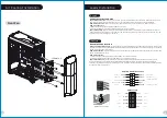
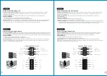
Leads Installation

Leads Installation Guide

Case LED Connection

 / On the front of the case, you can find some LEDs and switch leads. Please consult your user 

manual of your motherboard manufacturer, then connect these leads to the panel header on the motherboard.

USB 2.0 Connection

 / Please consult your motherboard manual to find out the section of “USB connection”.

USB 3.0 connection

 / 

1. Make sure your motherboard supports USB 3.0 connection.

2. Connect the USB 3.0 cable to the available USB 3.0 port on your computer.

Audio Connection

 / Please refer to the following illustration of Audio connector and your motherboard user manual. 

Please select the motherboard which used AC’97 or HD Audio(Azalia),(be aware of that your audio supports AC’97 or HD 

Audio (Azalia)) or it will damage your device(s).

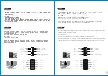
Anschlüsse herstellen

Gehäuse-LED-Verbindungen

 / Auf der Gehäusevorderseite finden Sie einige LEDs und Verbindungen. Bitte nehmen 

Sie die Gebrauchsanweisung Ihres Motherboard Herstellers zur Hilfe und schließen Sie diese Verbindungen an die Panel 

Header Belegung des Motherboards an.

USB 2.0 Anschluss

 / Bitte nehmen Sie die Gebrauchsanweisung Ihres Motherboards zur Hilfe und lesen Sie unter dem 

Kapitel „USB Anschlüsse“ nach.

USB 3.0 Anschluss

 / 

1. Stellen Sie sicher, dass Ihre Hauptplatine den USB 3.0 Anschluss unterstützt.

2. Verbinden Sie das USB 3.0 Kabel mit dem USB 3.0 Port auf Ihrem Computer.

Audio Anschlüsse

 / Bitte beachten Sie die folgende Abbildung der Audio Anschlüsse und die Anweisung in der 

Gebrauchsanweisung Ihres Motherboards. Bitte wählen Sie das Motherboard, das AC’97 oder HD Audio(Azalia) 

verwendet, (achten Sie darauf, dass Ihr Audio AC’97 bzw. HD Audio (Azalia unterstützt)). Andernfalls entstehen schwere 

Schäden an Ihrem(n) Gerät(en)!!!

USB 3.0 Connection

PRESENCE#

BLACK

SENSE1_RETURN

AUD GND

SENSE2_RETURN

YELLOW

BROWN

RED

PORT1 R
PORT2 R

PORT1 L

BLUE

PORT2 L

SENSE_SEND

KEY

PURPLE

GREEN

ORANGE

BLACK

AUDIO HD AUDIO Function

N

.

C

KEY

RED

2

WHITE

2

GREEN

2

BLACK

RED

1

WHITE

1

GREEN

1

BLACK

USB


F


unction

VCC1

D1-

D1+

GND

NC

VCC2

D2-

D2+

GND

KEY

English

Deutsch

Air Cooling Installation

Front Fan

120mm x 2 

16

/

02

/

0

3

A

發稿日期

版本

CHECK

Mike.Lin

16.02.0

3

其他特殊處理效果

DESIGN

Poki

16.02.0

3

產品料號

Versa N2

6

CA-1G

3

-00M1WN-00

說明書

產品名稱

印刷項目

騎馬釘

24

80

書寫紙

單色

表面處理

2

厚度

(g/m )

裝訂方式

材質

頁數

印刷色彩

規格樣式

整本

176

 mm

藍色 線 條 為尺 寸 標 示, 請 勿 印刷 上 去 !

125

 mm

刀 模 線

Summary of Contents for Versa N26

Page 1: ...2016 02 All other registered trademarks belong to their respective companies www thermaltake com User s Manual Benutzerhandbuch Mode d emploi Manual del usuario Manuale dell utente Manual do Utilizad...

Page 2: ...Screw 6 32 x 5 mm 6 8 For PSU PCI Slot 18 For 3 5 HDD Screw M3 x 5 mm 3 For 2 5 HDD main board foothold 6 For Hdd tray 8 For front fan 3 5 Device Installation 3 5 2 5 HDD Installation PCI Slot Usage R...

Page 3: ...ador de calor de la CPU es de 160 mm 6 3 pulgadas L mite de longitud para la tarjeta gr fica VGA El l mite de longitud para la tarjeta gr fica VGA en de 250 mm 9 8 pulgadas Attenzione Limite di altezz...

Page 4: ...a os parafusos na parte de tr s da caixa e abra o painel lateral T rk e Kasan n arkas ndaki vidalar kar n ve yan paneli a n English Place the power supply in proper location and secure it with screws...

Page 5: ...ckung des 5 25 Zoll Laufwerksschachts 3 Schieben Sie the 5 25 Zoll Einheit in den Laufwerksschacht um die Einheit zu sperren Anmerkung Dr cken Sie den 5 25 Zoll werkzeuglosen Mechanismus um die Einhei...

Page 6: ...mit den Schrauben Fran ais 1 Tirez le panneau de devant 2 Retirez le couvercle de la baie de lecteur 3 5 3 Ins rez le disque dur de 3 5 et s curisez le avec les vis Espa ol 1 Tire del panel frontal 2...

Page 7: ...durs 1 2 Espa ol 1 Extraiga la bandeja del disco duro 3 2 Sit e el HDD de pulgadas en la ubicaci n adecuada del HDD y aseg relo con tornillos 3 Vuelva a meter la bandeja del disco duro en su T rk e hu...

Page 8: ...los tornillos con un destornillador 2 Instale la tarjeta PCI en la ubicaci n adecuada y aseg rela con tornillos Italiano 1 Allentare le viti con un cacciavite 2 Installare la scheda PCI nella posizion...

Page 9: ...Ihres Motherboard Herstellers zur Hilfe und schlie en Sie diese Verbindungen an die Panel Header Belegung des Motherboards an USB 2 0 Anschluss Bitte nehmen Sie die Gebrauchsanweisung Ihres Motherboar...

Page 10: ...KEY RED2 WHITE2 GREEN2 BLACK2 RED1 WHITE1 GREEN1 BLACK1 USB Function VCC1 D1 D1 GND NC VCC2 D2 D2 GND KEY Fran ais Espa ol Guida di installazione dei contatti Connessione del LED del case Nella parte...

Page 11: ...97 HD Azalia LED LED POWER Switch USB 2 0 USB USB 3 0 1 USB 3 0 2 USB 3 0 USB3 0 AC 97 HD Azalia USB 2 0 USB USB 3 0 1 USB 3 0 2 USB 3 0 USB 3 0 AC 97 HD Audio Azalia AC 97 HD Audio Azalia LED LED USB...

Page 12: ...ds to power supplies Therefore selecting a suitable and reliable power supply becomes a necessary lesson for all PC users Why Choose Thermaltake Power Supply Quality From Within Every power supply uni...

Reviews: