background image

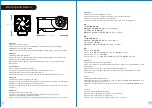
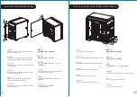
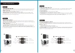
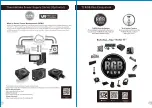
Side Panels Disassembly

English /
Remove the screws on the back of the chassis, 
and open the side panel

Deutsch /
Entfernen Sie die Schrauben auf der Rückseite 
des Gehäuses und öffnen Sie das Seitenteil

Français /
Enlevez les vis à l’arrière du châssis et ouvrez le 
panneau latéral

Español /
Extraiga los tornillos de la parte posterior de la 
caja y abra el panel lateral

Italiano /
Rimuovere le viti sulla parte posteriore dello 
chassis e aprire il pannello laterale

Português/
Remova os parafusos na parte de trás da caixa e 
abra o painel lateral

繁體中文

 /

移除機殼後方螺絲,將側窗打開

日本語 /
シャーシ背面のねじを取り外し、サイドパネ
ルを開きます

Русский /
Открутите винты на задней стенке корпуса 
и откройте боковую панель

简体中文 /
卸除机壳后方螺丝,将侧窗打开

Türkçe


/

Kasan

ı

n arkas

ı

ndaki vidalar

ı çı

kar

ı

n ve yan 

paneli aç

ı

n

ภาษาไทย /

ถอดสกรูที่ด้านหลังของแชสซีส์


แล้วเปิดแผงด้านข้าง

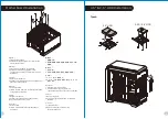
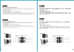
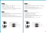
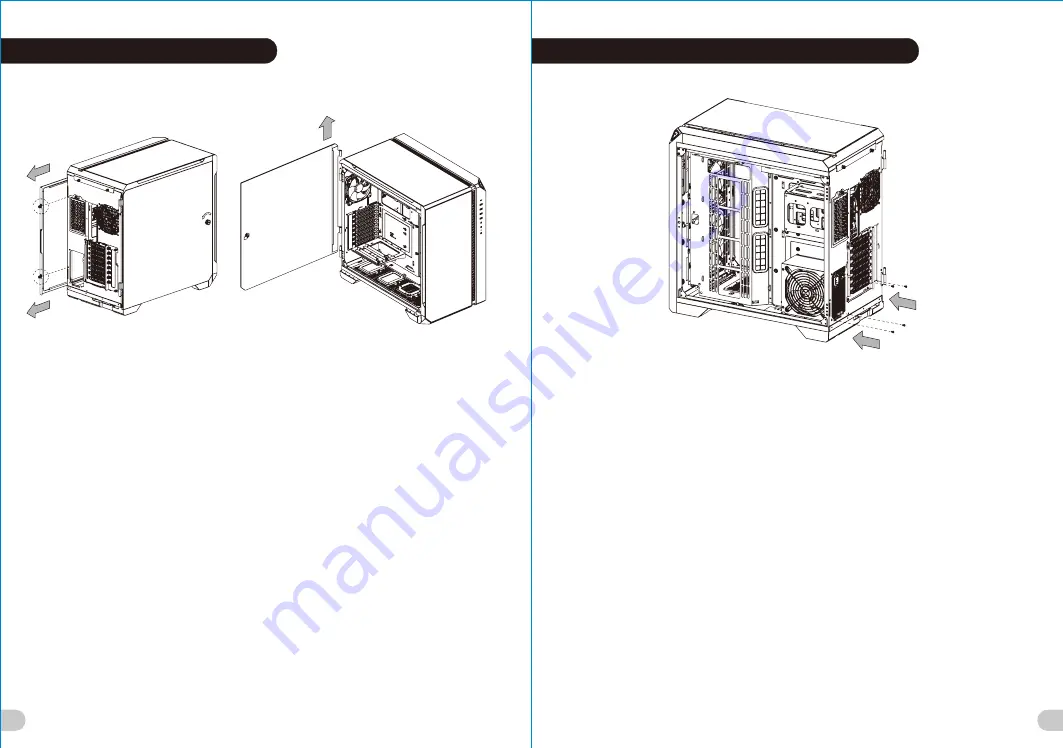
Power Supply Unit (PSU) Installation

English /

Deutsch /

Français /
Placez l’alimentation dans la position appropriée.

Español /
Instale la PSU en la ubicación correcta.

Italiano /

Place the PSU in proper location.

Platzieren Sie das Netzteil in der richtigen Position.

Posizionare la PSU in modo corretto.

Português/
Coloque o PSU na sua devida posição.

繁體中文

 /

简体中文 /

日本語 /

Русский /

Установите блок питания в надлежащее место.

Türkçe


/

將電源供應器放在正確的位置

将电源供应器放在正确的位置

PSU

を適切なロケーションに取り付けます。

PSU’yu, uygun konuma yerle

ş

tirin.

ภาษาไทย /

วาง PSU ในตำแหน่งที่เหมาะสม

藍色線條為尺寸標示,請勿印刷上去!

產品料號

CA-1Q6-00M1WN-00

View 51 TG ARGB

說明書

19/12/24

A

產品名稱

印刷項目

發稿日期

版本

騎馬釘

28

105

G

雙銅

單色

其他特殊處理效果

表面處理

2

厚度

(g/m )

裝訂方式

材質

頁數

印刷色彩

規格樣式

整本

CHECK

DESIGN

Poki

(19/12/24)

A

nna

(19/12/24)

刀模線

125

 mm

176

 mm

5

6

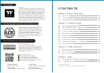
Summary of Contents for VIEW 51 TG ARGB

Page 1: ...одство пользователя kullanıcı elkitabı EEE Yönetmeliğine Uygundur คู มือการใช 2020 Thermaltake Technology Co Ltd All Rights Reserved 2020 01 All other registered trademarks belong to their respective companies www thermaltake com Tested To Comply With FCC Standards FOR HOME OR OFFICE USE Picture is for reference only view 51 TG ARGB ...

Page 2: ...ering the perfect user experience Thermaltake developed TT Premium with the essence of combining supreme quality products with a new logo design TT Premium is far more than just a guarantee of quality Behind the name it represents the passion in DIY Modding and Thermaltake s desire to be the most innovative brand in the PC hardware market To satisfy the demand of the high end PC users TT Premium f...

Page 3: ...dard PS2 PSU optional Fan Support Front 3 x 120mm 3 x 140mm 2 x 200mm Top 3 x 120mm 3 x 140mm 2 x 200mm Rear 1 x 120mm Right 3 x 120mm 2 x 140mm Bottom 3 x 120mm Without Water Pump Front 1 x 360mm 1 x 280mm Top 1 x 360mm 1 x 280mm Right 1 x 360mm 1 x 280mm Bottom 1 x 360mm Without Water Pump Clearance CPU cooler height limitation 175mm VGA length limitation 300mm With Water Pump 440mm Without Wate...

Page 4: ...Limitazione lunghezza VGA scheda aggiuntiva Assicurarsi che la lunghezza del VGA scheda aggiuntiva NON superi 300 mm 11 81 pollici Atenção Limite de altura para o dissipador do CPU O limite de altura para o dissipador do CPU é 175 mm 6 89 polegadas CPU 冷卻器的高度限制 請確保 CPU 冷卻器的高度不超過 175 mm 6 89 英吋 VGA 附加介面卡 的長度限制 請確保 VGA 附加介面卡 的長度不超過 300 mm 11 81 英吋 CPU 散热器高度限制 请确保 CPU 散热器的高度不超过 175 mm 6 89 英寸 VGA 附加卡...

Page 5: ...背面のねじを取り外し サイドパネ ルを開きます Русский Открутите винты на задней стенке корпуса и откройте боковую панель 简体中文 卸除机壳后方螺丝 将侧窗打开 Türkçe Kasanın arkasındaki vidaları çıkarın ve yan paneli açın ภาษาไทย ถอดสกรูที ด านหลังของแชสซีส แล วเปิดแผงด านข าง Power Supply Unit PSU Installation English Deutsch Français Placez l alimentation dans la position appropriée Español Instale la PSU en la ubicación correcta Ital...

Page 6: ... asegúrela con tornillos Italiano 1 Poggiare lo chassis 2 Installare la scheda madre nella posizione appropriata e fissarla con le viti Português 1 Deixe a caixa 2 Instale a motherboard no local adequado e aparafuse 繁體中文 1 將機殼平放 2 將主機板放置在合適的位置並用零件包中之螺 絲固定 日本語 1 シャーシを下に置きます 2 マザーボードを適切な場所に取り付け ねじで 固定します Русский 1 Раскройте системный блок 2 Установите материнскую плату в надлежащее место и закрепите...

Page 7: ...2 5 или 3 5 дюймовый жесткий 1 Extraiga la bandeja del disco duro диск в лоток и закрепите его винтами 2 Coloque el disco duro de 2 5 ó 3 5 en la 3 Установите лоток для жестких дисков bandeja y fíjelo con los tornillos обратно в каркас 3 Vuelva a meter la bandeja del disco duro en su hueco Türkçe 1 HDD tepsisini dışarı çekin Italiano 2 2 5 veya 3 5 sabit disk sürücüsünü tepsinin 1 Estrarre il vano...

Page 8: ...4 10 Red Yellow Green Cyan Blue White Purple Mode 11 18 RGB Red Yellow Green Cyan Blue White Purple Mode 20 26 Red Yellow Green Cyan Blue White Purple Mode 19 Mode 27 Long press on RGB button for 3 seconds fan will blink twice which now are controlled by MB software And vice versa Aura Addressable Strip Header s Addressable RGB LED Header s AORUS RGB Fusion with Digital LEDs ASUS GIGABYTE JRGB str...

Page 9: ...0mm x 2 Bottom 120mm x 3 120mm x 3 or 140mm x 2 Top 360 x 30 mm or 280 x 55 mm Bottom 360 x 30 mm Front 360 x 30 mm or 280 x 55 mm Right 360 x 64 mm or 280 x 55 mm Top 120mm x 3 or 140mm x 3 or 200mm x 2 Right 120mm x 1 Back The Radiators are recommended to mount inside the chassis 13 14 ...

Page 10: ...Liquid Cooling Installation 200mm Fan Radiator 360mm 200mm Fan Pump Installation or Rubber 15 16 ...

Page 11: ...SENSE2_RETURN SENSE2_RETURN YELLOW YELLOW BROWN BROWN RED RED PORT1 R PORT1 R PORT2 R PORT2 R PORT1 L PORT1 L BLUE BLUE PORT2 L PORT2 L SENSE_SEND SENSE_SEND KEY KEY PURPLE PURPLE GREEN GREEN ORANGE ORANGE BLACK BLACK AUDIO HD AUDIO Function AUDIO HD AUDIO Function English Deutsch Guide d installation des fils A Connexion des voyants du boîtier Sur la face avant du boîtier vous trouverez plusieurs...

Page 12: ...omputador C Ligação Áudio Consulte a imagem seguinte do conector Áudio e o manual de utilizador da sua motherboard Seleccione a motherboard que utiliza AC 97 ou HD Áudio Azalia verifique se a sua placa de áudio suporta AC 97 ou HD Áudio Azalia ou irá danificar o s seu s dispositivo s Italiano Português 線材安裝說明 A 機殼LED連接方式 在機殼前方的面板後面 可以找到一些LED與開關線材 POWER Switch 請參考主機板使用說明 書 並將機殼上的線材正確地連接到主機板上 這些線材通常...

Page 13: ...na bağlayın B USB 3 0 Bağlantısı 1 Ana kartınızın USB 3 0 bağlantısını desteklediğinden emin olun 2 USB 3 0 kablosunu bilgisayarınızdaki kullanılabilir USB 3 0 bağlantı noktasına bağlayın C Ses Bağlantısı Lütfen aşağıdaki Ses konektörü resmine ve anakartınızın kullanım kılavuzuna bakın Lütfen AC 97 veya HD Audio Azalia spesifikasyonunu kullanan bir anakart seçin ses sisteminizin AC 97 veya HD Audi...

Page 14: ...24 23 ...

Reviews: