background image

WARRANTY

All equipment and accessories are warranted by Thermaltronics to be free from defects in materials 

and workmanship as follows:
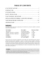
Part Number    

Description

Warranty Period

TMT-AF100

Auto Solder Feeder

1 Year

AF-HPK-1, AF-HPK-2, AF-HPK-3

Guide Pipe Assembly

30 Days

AF-HDL-1, AF-HDL-2, AF-HDL-3

Hand Piece Holder

1 Year

AF-NOZ-1       

Nozzle Pack

30 Days

AF-PEDAL-1

Auto Feeder Switch

1 Year

AF-POWER-1

AC Power Adapter

1 Year

This warranty does not apply to equipment or goods which have been tampered with, misused, 

damaged through improper installation or used in a manner contrary to supplier instructions. 

Normal “wear and tear” of equipment or goods is not covered by this warranty. If the product 

should become defective within the warranty period, Thermaltronics will repair or replace it free 

of charge at its sole option. Warranty period is from the date of purchase by the original owner. 

If the date of purchase cannot be substantiated the date of manufacture will be used as the 

start of the warranty period.

TABLE OF CONTENTS

AF-KIT SPECIFICATIONS ........................................................................... 1

INTRODUCTION .......................................................................................... 1

SYSTEM FEATURES ................................................................................ 1-2

SAFETY PRECAUTIONS ............................................................................. 2

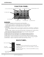
FUNCTION PANEL / BACK PANEL ............................................................. 3

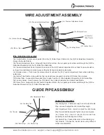
WIRE ADJUSTMENT ASSEMBLY, GUIDE PIPE ASSEMBLY ..................... 4

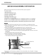
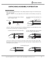
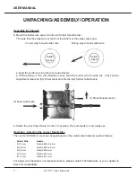
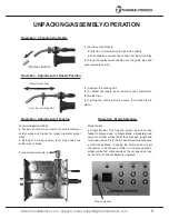
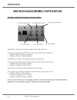
UNPACKING/ASSEMBLY/OPERATION ................................................... 5-9

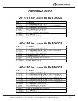
ORDERING GUIDE .....................................................................................11

WARNING: 

This appliance is not intended for use by persons (including children) with reduced physical, sensory or mental 
capabilities, or lack of experience and knowledge, unless they have been given supervision or instruction 
concerning use of the appliance by a person responsible for their safety.
Children should be supervised to ensure that they do not play with the appliance.

Summary of Contents for AF-KIT

Page 1: ...USER MANUAL AF KIT AUTO SOLDER FEEDER KIT www thermaltronics com ...

Page 2: ......

Page 3: ...ome defective within the warranty period Thermaltronics will repair or replace it free of charge at its sole option Warranty period is from the date of purchase by the original owner If the date of purchase cannot be substantiated the date of manufacture will be used as the start of the warranty period TABLE OF CONTENTS AF KIT SPECIFICATIONS 1 INTRODUCTION 1 SYSTEM FEATURES 1 2 SAFETY PRECAUTIONS ...

Page 4: ... 46mm sec Solder Feed Quantity 0 14mm Solder Return Quantity 0 14mm Solder Feeder Mode Single Continuous Usable Solder Diameter Φ0 5 Φ0 6 Φ0 8 Φ1 0 Φ1 2 Size W x H x D 150mm x 165mm x 130mm Weight 1 5 KG Input Line Frequency 50 60 Hz Certification Marks CE INTRODUCTION Congratulations on your purchase of the AF KIT auto feeder kit This unit has been tested and inspected by Thermaltronics prior to ...

Page 5: ...loosen or secure the hand piece in place SAFETY PRECAUTIONS Warning 1 Use this equipment in a well ventilated area away from combustible equipment 2 Place handle in stand when not in use 3 Do not damage the guide pipe by bending or twisting it 4 Do not allow the solder tube to be bent at a severe angle Otherwise it will become clogged with solder 5 Handle with care Never drop or sharply jolt the u...

Page 6: ... Speed Indicator LED When indicator light is on the LCD Display will display the Speed value 1e Length Indicator LED When indicator light is on the LCD Display will display the Length value 1f Return Indicator LED When indicator light is on the LCD Display will display the Return value 1g Return Buttons Increase or decrease the set return solder wire length Value can be between 00 and 99 1h Length...

Page 7: ... Tube A conduit to allow solder wire to pass from the 3 Wire Adjustment Assembly to the Guide Pipe 3g Locking Screw Used to secure the 3f Solder Tube in place inside the 3e Solder Tube Nozzle 3h Driver Gear Along with the 3b Tension Adjustment Gear the two gears push solder wire through the 3 Wire Adjustment Assembly into 5 Guide Pipe Assembly 3c Tension Adjustment Knob 3d Release Lever 3g Locking...

Page 8: ... auto solder feeder from its box and place on a suitable work bench 2 Remove the AF HDL X2 Hand Piece Holder from the box and attach to the right side of the TMT AF100 auto solder feeder 3 Remove the AF PEDAL 1 Auto Feeder Switch from the box See Back Panel Connect to the 2b Switch Connection Port on the back panel of the auto solder feeder 4 Remove the AF POWER 1 AC Power Adapter from the box See...

Page 9: ...w driver to secure the 4C Guide Clip to the soldering hand piece AF KIT 1M AF KIT 2T AF KIT 3K AF KIT 3KM AF KIT 3P AF KIT 3PM AF KIT 3SM No assembly of Guide Pipe is required the Guide Pipe Assembly is already attached to the soldering hand piece by default 1 Remove the hand piece top by rotating in counter clockwise motion 2 Install the Guide Pipe Assembly to the hand piece 1 Push the Guide Clip...

Page 10: ...ube Nozzle 9 Switch the 2a Power Switch to the on position The auto feeder is now ready use Operation Selecting the correct Nozzle Size The nozzle AF NOZ 1 must be changed based on the solder wire diameter used as follows Solder Wire Nozzle Φ 0 5mm Nozzle Φ0 5 0 6mm Φ 0 6mm Nozzle Φ0 5 0 6mm Φ 0 8mm Nozzle Φ0 8mm Φ 1 0mm Nozzle Φ1 0mm Φ 1 2mm Nozzle Φ1 2mm For solder wire diameters not mentioned a...

Page 11: ...ew Locking Nut Adjust Guide Pipe Operation Adjustment of Tension Operation Mode Selection Mode Selection Mode Switch Single Mode Pushing the switch up will set the feeder to Single mode In Single Mode a predetermined amount of solder will be fed at the set speed length and return feed when the 2 Auto Feeder Switch is activated Continuous Mode Pushing the switch down will set the feeder to Continuo...

Page 12: ...l of 100 units Each unit is 0 14mm 1 Minimum Length 00 shortest 0 14mm 2 Maximum Length 99 longest 14mm Return Buttons Increase or decrease the return solder wire length The value can be set between 00 and 99 for a total of 100 units Each unit is 0 14mm 1 Switched Off 00 no return 0 00mm 2 Minimum Length 00 shortest 0 14mm 3 Maximum Length 99 longest 13 86mm Note To prevent solder wire from cloggi...

Page 13: ...y for TMT 5000S AF HDL 2 Hand Piece Holder for TMT 5000S AF NOZ 1 Nozzle Pack Φ0 5 Φ0 6 Φ0 8 Φ1 0 Φ1 2 AF PEDAL 1 Auto Feeder Switch AF POWER 1 AC Power Adapter 18V2A PART DESCRIPTION AF KIT 3 Auto Solder Feeder Kit for TMT 2000S AF KIT 3K Auto Solder Feeder Kit w SHP K Soldering Handle for TMT 2000S AF KIT 3KM Auto Solder Feeder Kit w SHP KM Soldering Handle for TMT 2000S AF KIT 3P Auto Solder Fe...

Page 14: ......

Page 15: ......

Page 16: ...Support Email support thermaltronics com www thermaltronics com ...

Reviews: