Thermann Installer's Manual
Gas Continuous Flow Condensing Water Heaters
12
This unit generates condensate continuously at a rate of up to 5 litres per hour as a by-
product of the highly efficient gas burner system.
This condensate must be drained via a pipe to a suitable point of discharge. As the
condensate is a by-product of gas combustion, it is mildly acidic.
For this reason, copper tube and fittings MUST NOT be used, as they will corrode.
The unit has an in-built condensate neutralizer to make the condensate safe for discharge.
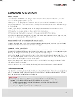
It is recommended to use DN15 high pressure PVC pipe and fittings for the condensate
drain line.
CONDENSATE DRAIN
IMPORTANT CONSIDERATIONS FOR THE CONDENSATE DRAIN PIPE
The content of AS/NZS 3500 'Temperature/Pressure Relief and Expansion Control Valve
Drain Lines' has been used as a guide in preparing these considerations.
DRAINAGE OF CONDENSATE WATER
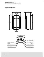
Condensate drain outlet connection, R1/2" (15mm) BSP male nylon.
Note: the white plastic shipping cap MUST BE removed from the condensate drain outlet
prior to water heater operation. In the case that white-ish stone pieces (calcium carbonate)
comes out of the neutralizer when the cap is removed, they should be discarded.
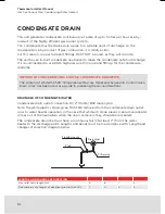
The condensate drain line must have a continuous fall (of at least 2°) from the water
heater to the discharge point. Lengths and bends must be in accordance with 'Length and
changes of direction' diagram below.
LENGTHS AND CHANGES OF DIRECTION
Max relief drain length (m)
9
8
7
6
Max numbers of changes of direction (greater than 45°)
3
4
5
6
Drain outlet
2° fall
Fix with pipe clip
PVC piping
Summary of Contents for 26LP50C
Page 2: ...Thermann Installer s Manual Gas Continuous Flow Condensing Water Heaters ...
Page 27: ...27 27 27 ...
Page 28: ...20832270 K ...


