background image

DOC NO. 81028 

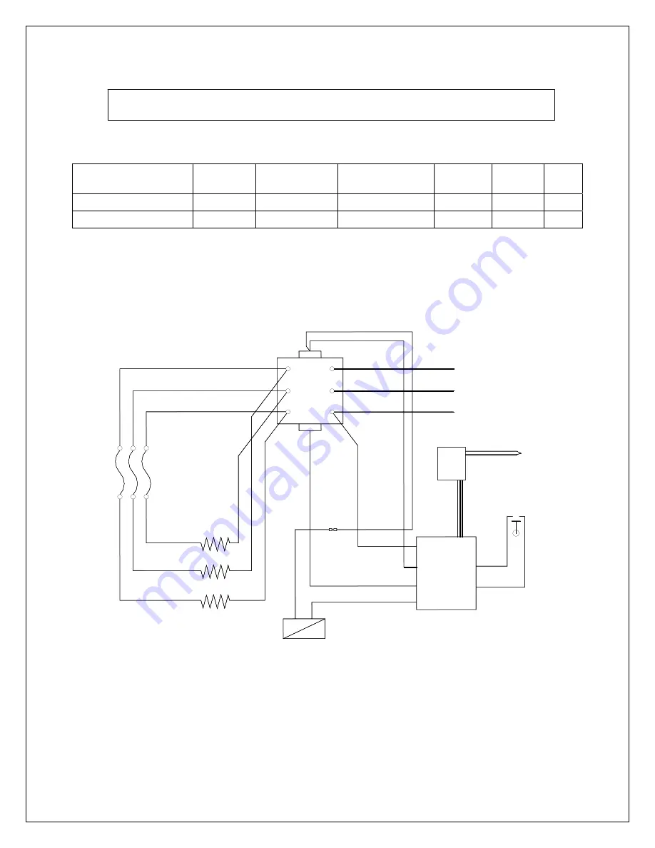
7 OF 11 

Rev D 08/17/06 NJL 

3

2

HEATER A

1

FUSES

208/240V 

SOLENOID

CONTACTOR

1

2

3

1

2

3

T1

L1

T2

T3

L2

L3

TOUCH

PAD
PCB

POWER
SUPPLY

PCB

208/240V

J3

J7  

(J6)

J2

J1

J5

J4

FLOAT

SWITCH

230 VAC
3 PHASE

TEMPERATURE SENSOR

LINE IN

LINE IN

LINE IN

208/240V COIL

RED

RED

ORN

ORN

WHT 14

RED 14

RED 14

WHT 14

BLK

 6

BLK

 6

BLK

 6

BLK 6

BLK 6

BLK 6

SOLDERLESS 

CRIMP

BLK 14

HEATER B

HEATER C

BLK 6

BLK 6

BLK 6

Electrical Instruction 


Wire sizes recommended by National Electric code. Minimum wire temperature rating 90C. 


Generator Model 

Phase 

Wire Gauge

Breaker Size 

Fuse 

Cubic 

Feet 

kW 

5500-1203 3  4 

90 50A 

1200 

30 

5500-1503 3  4 

110 60A 

1500 

36 


1.


Turn off all electricity to the working area at the main breaker panel. 

 
2.


Connect 

230-volt A.C.

 electrical lines to wire labeled 1, 2 and 3 in junction box on generator (see 

Figure 2). 


NOTE: All electrical wiring must be done per local electrical codes. 

Figure 2 

Summary of Contents for PowerPak Series 240V

Page 1: ...UNCTION WITH YOUR THERMASOL UNIT WITHOUT CONSULTING WITH YOUR ALLERGIST OR DOCTOR BEFORE USE THESE PRODUCTS MAY BE HAZARDOUS TO YOUR HEALTH YOUR SHOWER MAY BE A SLIP AND FALL HAZARD CHECK WITH YOUR CONTRACTOR OR TILE MANUFACTURER REGARDING THE SAFE USE OF YOUR FLOORING IN A STEAM APPLICATION SLIPPING AND FALLING INTO THE STEAM HEAD ITSELF OR INTO THE STREAM OF STEAM EMITTING FROM THE STEAM HEAD WI...

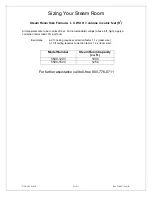
Page 2: ...in units of feet For non standard ceilings above 8 ft high apply a correction factor add 10 per foot Examples a 9 ft ceiling requires correction factor 1 1 x room size a 10 ft ceiling requires correction factor 1 2 x room size Model Number Steam Room Capacity cu ft 5500 1203 1000 5500 1503 1250 For further assistance call toll free 800 776 0711 ...

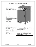
Page 3: ... quantities per Instructions Copper tubing or pipe Wire cap nuts Flex conduit Brass or copper tee Connection plug Tools Needed Pipe wrench Tubing cutter Flaring tool if flared fittings are used Pipe thread cap Wire cutters or wire strippers Adjustable wrench Screwdrivers Philips Regular Solder Flux 3 16 1 5 masonry drill bits Drill motor Propane Torch Other tools as required All Thermasol steam ge...

Page 4: ...ut water serious damage may result This possible damage is not covered under Thermasol s limited warranty Note Failure to follow specific installation instructions will cause the warranty to be void Water Inlet Refer to Figure 1 for the following 1 Connect tee to the hot or cold water line Install copper pipe or tubing to the tee If an in line filter is to be installed on the water line to the gen...

Page 5: ...nstall a 1 M I P on the end of the 1 pipe for the steamhead 3 Attach the steamhead and escutcheon to the copper pipe CAUTION Do not obstruct the steam line with any shut off valves plugs or caps ALL Thermasol steam generators are designed to build NO PRESSURE The steam line can run up down or horizontal but cannot run down and then up If it does a steam trap will be produced at the low point block...

Page 6: ...ING NEVER ATTEMPT TO FILL AROMA RESERVOIR ON THE STEAM HEAD WHEN UNIT IS IN THE ON POSITION SEVERE BURNS WILL OCCUR WARNING DO NOT USE THERMASOL AROMA THERAPY OILS OR SKIN CARE PRODUCTS OR ANY PRODUCT IN CONJUNCTION WITH YOUR THERMASOL UNIT WITHOUT CONSULTING WITH YOUR ALLERGIST OR DOCTOR BEFORE USE THESE PRODUCTS MAY BE HAZARDOUS TO YOUR HEALTH WARNING YOUR SHOWER MAY BE A SLIP AND FALL HAZARD CH...

Page 7: ...SOLDERLESS CRIMP BLK 14 HEATER B HEATER C BLK 6 BLK 6 BLK 6 Electrical Instruction Wire sizes recommended by National Electric code Minimum wire temperature rating 90C Generator Model Phase Wire Gauge Breaker Size Fuse Cubic Feet kW 5500 1203 3 4 90 50A 1200 30 5500 1503 3 4 110 60A 1500 36 1 Turn off all electricity to the working area at the main breaker panel 2 Connect 230 volt A C electrical l...

Page 8: ...he generator With the top cover removed see Figure 3 connect the control sensor wires using wire nuts to the two loose wires on the back of the control panel 5 Replace top access cover Turn on both water and power to the generator 6 Test the touch pad to ensure it is properly wired If any technical problems arise call toll free 800 776 0711 Failure to follow installation instructions specifically ...

Page 9: ...ING NEVER ATTEMPT TO FILL AROMA RESERVOIR ON THE STEAM HEAD WHEN UNIT IS IN THE ON POSITION SEVERE BURNS WILL OCCUR WARNING DO NOT USE THERMASOL AROMA THERAPY OILS OR SKIN CARE PRODUCTS OR ANY PRODUCT IN CONJUNCTION WITH YOUR THERMASOL UNIT WITHOUT CONSULTING WITH YOUR ALLERGIST OR DOCTOR BEFORE USE THESE PRODUCTS MAY BE HAZARDOUS TO YOUR HEALTH WARNING YOUR SHOWER MAY BE A SLIP AND FALL HAZARD CH...

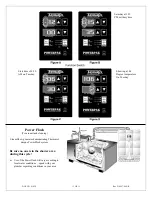
Page 10: ...e week press the Day Select button the day you started with to ensure you have all the days programmed 5 Now you will set the Powerflush program You must set the Flush time at least hour past the Steam Stop time when no one is inside the steam room Press the Clock Start Stop button once You should see the light next to the Start Time come on and the light next to the flush come on Using the arrows...

Page 11: ...sol unique PowerFlush system Be sure no one is in the shower area during this cycle Use of the Powerflush will vary according to local water conditions speak with your plumber regarding conditions in your area Saturday at 3 35 PM military time Start time of 6 30 AM on Tuesday Showing a 106 Degree temperature On Tuesday ...

Reviews: