Installation and Operation Handbook Installation
1.4
MOTORISED VALVE CONNECTIONS
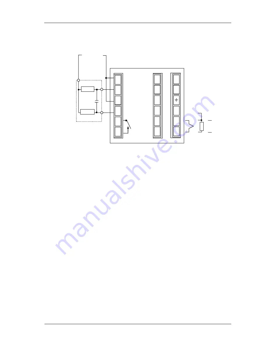
Motorised valves are wired to relay, or triac, outputs installed in module positions 1 and 2. The convention is to
configure Output 1 as the RAISE output and Output 2 as the LOWER output. The controller does not require a
position feedback potentiometer.
Figure 1-8: Motorised valve controller connections
RTD/
Pt100
Line
Neutral
Ground
+
−
+
PV
−
Motor supply
LOWER
RAISE
Motorised
valve
T/C
Comms
JA
JF
BA
HA
HB
HC
HD
HE
HF
1A
1B
2A
2B
3A
3B
L
N
V1
V+
V-
mV
HA025041 issue 12 Aug 14
1-9
Summary of Contents for XST-2-0-12-1V1-E28
Page 16: ...12 FURNACE TROUBLE SHOOTING ...
Page 27: ...ɸ ...
Page 28: ...ɸ ...
Page 29: ......
Page 30: ......
Page 31: ...3216 3208 3204 User Manual 3200 Range Process Controller HA028651 11 Aug 2012 ...
Page 170: ...User Manual 3200 Series 138 Part No HA028651 Issue 11 0 July 12 21 Certificate of Conformity ...
Page 171: ......
Page 173: ...Model 2416 Process Controller User Manual Part No HA025041_12 Date August 2014 ...
Page 174: ...This page is intentionally blank ...
Page 259: ...This page is intentionally blank ...


