3200 Series User Manual
1 Part No HA028651 Issue 11.0 CN28836 July-12
3200 Series PID Temperature Controllers
User Manual Part Number HA028651
Issue 11.0 July-12
Includes 3216, 3208, 32h8 and 3204 Controllers.
Contents
1.
Installation and Basic Operation ....................................................................................................... 6
1.1
What Instrument Do I Have? .............................................................................................................................. 6
1.2
Unpacking Your Controller ................................................................................................................................ 6
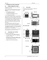
1.3
Dimensions ........................................................................................................................................................ 6
1.4
Step 1: Installation ............................................................................................................................................ 7
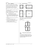
1.4.1
Panel Mounting the Controller ......................................................................................................................................................................... 7
1.4.2
Panel Cut Out Sizes .............................................................................................................................................................................................. 7
1.4.3
Recommended minimum spacing of controllers ........................................................................................................................................ 7
1.4.4
To Remove the Controller from its Sleeve ................................................................................................................................................... 7
1.5
Order Code ........................................................................................................................................................ 8
2.
Step 2: Wiring ................................................................................................................................... 9
2.1
Terminal Layout 3216 Controller ........................................................................................................................ 9
2.2
Terminal Layout 32h8 Controllers ...................................................................................................................... 10
2.3
Terminal Layout 3208 and 3204 Controllers ........................................................................................................ 11
2.4
Wire Sizes .......................................................................................................................................................... 12
2.5
Precautions ........................................................................................................................................................ 12
2.6
Sensor Input (Measuring Input) ......................................................................................................................... 12
2.6.1
Thermocouple Input ............................................................................................................................................................................................ 12
2.6.2
RTD Input ................................................................................................................................................................................................................ 12
2.6.3
Linear Input (mA or mV) .................................................................................................................................................................................... 12
2.6.4
Two-Wire Transmitter Inputs ............................................................................................................................................................................ 12
2.7
Input/Output 1 & Output 2 ................................................................................................................................ 13
2.7.1
Relay Output (Form A, normally open) ......................................................................................................................................................... 13
2.7.2
Logic (SSR drive) Output .................................................................................................................................................................................... 13
2.7.3
DC Output .............................................................................................................................................................................................................. 13
2.7.4
Triac Output ........................................................................................................................................................................................................... 13
2.7.5
Logic Contact Closure Input (I/O 1 only) ...................................................................................................................................................... 13
2.8
Remote Setpoint Input ....................................................................................................................................... 13
2.9
Output 3 ............................................................................................................................................................ 13
2.10
Summary of DC Outputs .................................................................................................................................... 13
2.11
Output 4 (AA Relay) ........................................................................................................................................... 14
2.12
General Note About Relays and Inductive Loads ................................................................................................ 14
2.13
Digital Inputs A & B ........................................................................................................................................... 14
2.14
Current Transformer .......................................................................................................................................... 14
2.15
Transmitter Power Supply .................................................................................................................................. 14
2.16
Digital Communications ..................................................................................................................................... 15
2.17
Controller Power Supply .................................................................................................................................... 16
2.18
Example Heat/Cool Wiring Diagram ................................................................................................................... 16
2.18.1
Example CT Wiring Diagram ........................................................................................................................................................................ 16
3.
Safety and EMC Information ............................................................................................................. 17
3.1
Installation Safety Requirements ....................................................................................................................... 17
4.
Switch On .......................................................................................................................................... 19
4.1
New Controller .................................................................................................................................................. 19
4.1.1
Quick Start Code .................................................................................................................................................................................................. 19
4.2
To Re-Enter Quick Code mode ........................................................................................................................... 20
4.3
Pre-Configured Controller or Subsequent Starts ................................................................................................ 20
4.4
Front Panel Layout ............................................................................................................................................. 21
4.4.1
To Set The Target Temperature. ...................................................................................................................................................................... 21
4.4.2
Alarms ...................................................................................................................................................................................................................... 21
4.4.3
Alarm Indication ................................................................................................................................................................................................... 21
4.4.4
Auto, Manual and Off Mode ............................................................................................................................................................................. 22
4.4.5
To Select Auto, Manual or Off Mode ............................................................................................................................................................. 22
4.4.6
Level 1 Operator Parameters ............................................................................................................................................................................ 23
5.
Operator Level 2 ................................................................................................................................ 23
Summary of Contents for XST-2-0-12-1V1-E28
Page 16: ...12 FURNACE TROUBLE SHOOTING ...
Page 27: ...ɸ ...
Page 28: ...ɸ ...
Page 29: ......
Page 30: ......
Page 31: ...3216 3208 3204 User Manual 3200 Range Process Controller HA028651 11 Aug 2012 ...
Page 170: ...User Manual 3200 Series 138 Part No HA028651 Issue 11 0 July 12 21 Certificate of Conformity ...
Page 171: ......
Page 173: ...Model 2416 Process Controller User Manual Part No HA025041_12 Date August 2014 ...
Page 174: ...This page is intentionally blank ...
Page 259: ...This page is intentionally blank ...


