48 THERMEX
PRO LINK I
M P550193900011122018
Es
Pañ
OL
»
P
R
O
L
INK
B
ASIC
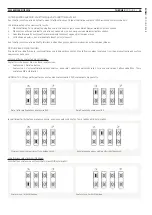
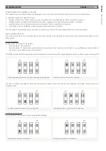
CONEXIÓN DEL RECEPTOR
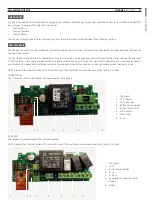
El receptor se conecta según el siguiente diagrama:
Cuando la corriente esté conectada, el diodo rojo se enciende.
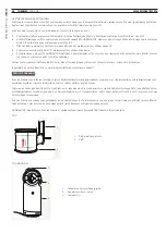
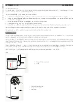
CONEXIÓN DEL EMISOR
El emisor se conecta en el suministro de corriente del extractor. El emisor se conecta según el siguiente diagrama:
Cuando la corriente esté conectada, el diodo verde "Power" se enciende.
L
N
N F1 F2
230 V out
for valve
COMM
NO NC
COMM
NO NC
Relay 2
Relay 1
Pair button
Fuse
Diode
Dipswitch
230 V in
Button
Pair
Fuse
Diode
Set point
Dipswitch
Diode
Power
N
L
N
L
230 V in
230 V output
for range hood
Button
Set point


