DTH Electric Boilers USE & CARE MANUAL
(Revision June 2014)
, Page
6.
Section 3 : INSTALLATION
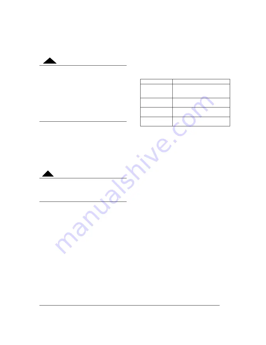
The manufacturer’s warranty does not cover
any damage or defect caused by installation,
or attachment, or use of any special
attachment other than those authorized by
the manufacturer, into, onto, or in
conjunction with the boiler. The use of such
unauthorized devices may shorten the life of
the boiler and may endanger life and
property. The manufacturer disclaims any
responsibility for such loss or injury
resulting from the use of such unauthorized
devices
3.1 SECURITY CONSIDERATIONS
Domestic and commercial installations have a
maximum design operating pressure limited to
30 psi (207 kPa) or 60psi (414kPa) by a safety
relief valve.
Boiler maximum operating temperature is 190°F
by design. This boiler is designed to be used
only in a hot water heating system.
The heat transfer medium must be water or
other non-toxic fluid. An antifreeze solution
with propylene glycol specially formulated
for heating system could be used up to a
maximum concentration of 50%
3.2 LOCATION
The electric boiler should be installed in a clean,
dry location. Long hot water lines should be
insulated to conserve energy. The electric boiler
and water lines should be protected from
exposure to freezing temperatures.
The electric boiler must be installed horizontally
directly on the floor or wall. Supporting legs are
included but wall mounting brackets are not.
The electric boiler must be located or protected
so as not to be subject to physical damage, for
example, by moving vehicles, area flooding, etc.
All models can be installed on combustible floors
and in alcoves. Ambient temperature must not
exceed 80°F or 27°C.
3.3 CLEARANCE
Minimum clearances for adequate inspection
and servicing are listed in the following table:
Table 4: Boiler clearance
Left side
14 inches
Right side
14 in.(78to144kW 480&600v)
(54to96kWx 240v)
0in. Other models
Top & bottom of
the boiler
12 inches
Front side of the
boiler
24 inches
Back side of the
boiler
0 inch
3.4 SYSTEM SETUP
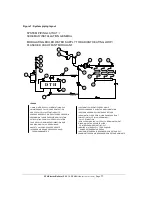
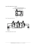
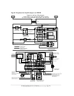
The recommended piping arrangement is shown
in Figure 4, 5 and 6 including the pump,
expansion tank, drain valve, pressure relief
valve, air vent, flow check valve and pressure-
temperature gauge. Details about each item
follow.
3.4.1 Boiler connections
This electric boiler may be connected
individually or in parallel with other boilers. If two
or more boilers are connected, the “reverse-
return piping” method (whereby the boiler with
the first return inlet also has the last supply
outlet and so forth until the last return inlet
corresponds to the first supply outlet) should be
used to connect the boilers in parallel, to ensure
an equal water flow rate through each boiler.
The boiler water supply, located on the top side,
and the boiler water return, located on the
bottom side of the boiler are steel pipes (male
NPT threaded connection) where supply and
return line connections are to be made.
Installing a union is recommended on the boiler
water supply and return lines to facilitate boiler
disconnection for servicing.
Dielectric unions are required for protection of
the boiler and piping if dissimilar pipe material
such as galvanized steel and copper are
present.
WARNING
!
CAUTION
!


