VOLTMAX ELECTRIC BOILER Installation and Operation Manual
(
Revised June 2017)
, Page
66.
SECTION 6 : TROUBLESHOOTING
The troubleshooting section shows the various
error messages that can occur during abnormal
operation of the boiler.
It is possible to change the limits of some alarms
on the controller in the
Limit Setting.
6.1 WARNING LIGHTS
The LEDs above the navigation buttons indicate
3 different boiler states.
Active
warning
light
Boiler status
Green
Normal operation of the boiler
Yellow
One or more alarms are active.
These alarms do not prevent the
operation of the boiler; the boiler
continues to operate in normal
mode.
Ex. The controller detects a problem
with the amperage reading sensor.
Red
A critical alarm is active,
accompanied by the buzzer (if
active).
Ex. A high limit alarm is active
6.2 OPERATING PROBLEM
IDENTIFICATION
An alarm log is available in the
BOILER
CONFIG / ALARM / ALARM LOG
. Each alarm
is recorded with its alarm code, the time and
date. The register can record up to 30 alarms.
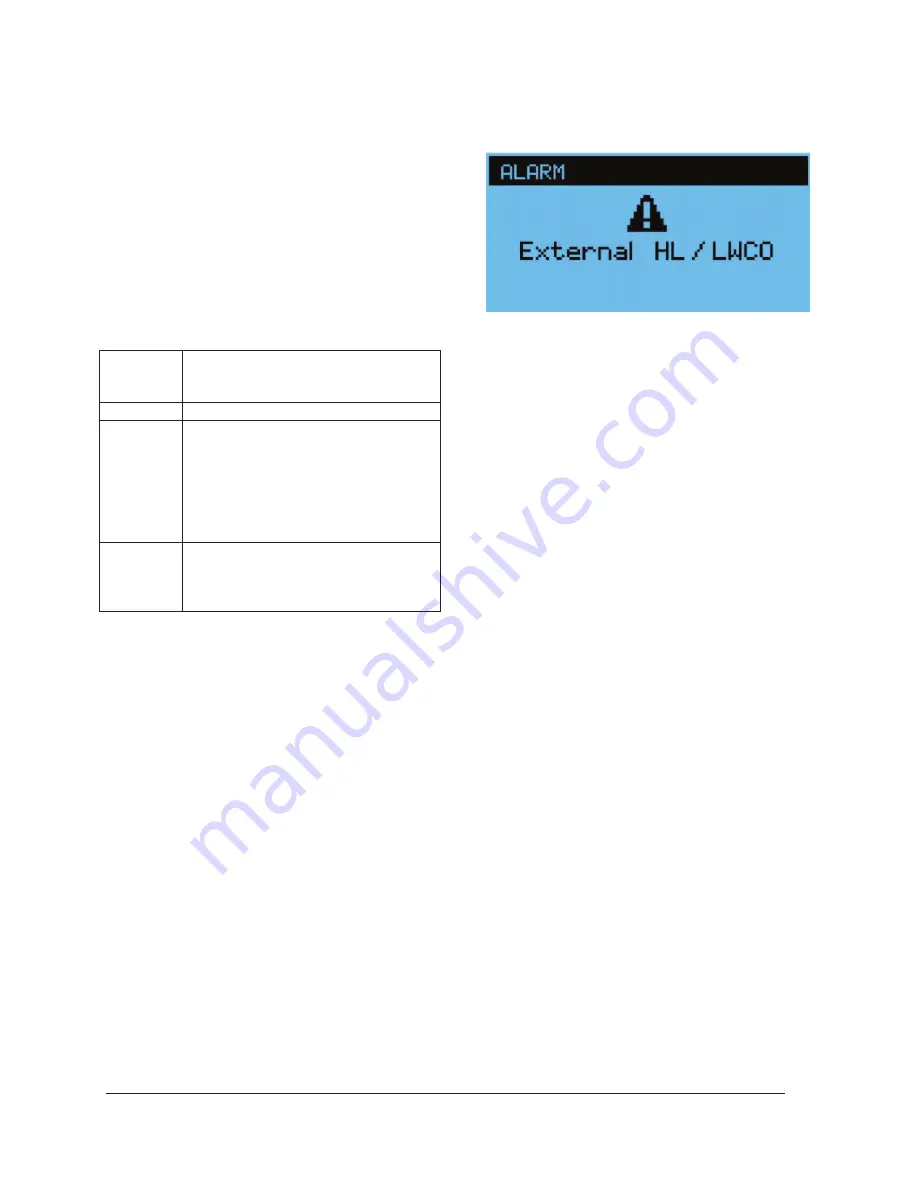
6.2.1 EXTERNAL HL / LWCO
When this alarm is present, the indicator light to
the left of the boiler lights red.
This alarm happens when one of the two
external sensors (External fault Low Water Cut
Off or External High limit) is triggered.
Look for the cause of this contact opening which
normally occurs when there is a lack of water in
the boiler according to the low water level
sensor (Standard on 120 kW models and higher)
or when the high temperature limit control
detects a temperature higher than 210°F.
The external alarm contact will be activated
immediately if it has been activated (
Ext. Alarm
Contact
) in the Alarm menu. The heating
elements stop working and will start again when
the water level returns to normal. If this alarm
happens 3 times in 1 hour, the boiler will be set
in
Lock out
mode.
6.2.2 SENSOR ( SE
)
The
Sensor
alarm is activated when the
controller detects a problem with a sensor.
This alarm usually appears with another alarm,
for example the flow rate alarm (F) and the
sensor alarm (SE), this help target a flow sensor
problem, for example.
See Table 13 for comparison of Resistance
measurements against temperature for the
outdoor sensor.
6.2.3 LOW LIMIT ( LL
)
The
LL alarm
is activated when the temperature
differential between the set-point temperature
and the boiler output temperature is higher than
Delta T.LL
and this period is higher than the
LL
delay
.
The heating elements remain in operation. The
screen will automatically return to its normal
state. When the temperature of the boiler
approaches the set temperature.
6.2.4 FLOW ( F )
(Available only on SCR model)
The
flow
alarm is triggered when the theoretical
flow calculation is below the manufacturer's
authorized flow limit.
6.2.5 CURRENT ( A )
(Available only on SCR model)
The
Current
alarm is triggered when there is a
difference of more than 20% between the
measured current
(Available only on SCR


