background image

10

Specifications

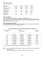
Model - OTF - ITF

510

801

1010

1600

Gross Input

140,000

210,000

280,000

350,000

Gross Output - BTU/Hr.

109,200

163,800

218,400

273,000

Flue Pipe Dia.

6"

6"

8"

8”

Firing Rate - GPH

1.00

1.50

2.00

2.50

Width OTF-ITF

22"

22"

26-1/4"

26-1/4"

Length OTF-ITF

31"

31"

34"

34"

Height OTF-ITF

38-1/2"

38-1/2"

45"

45"

STANDARD EQUIPMENT

OTF 

— 

Al

umi

num 

j

ac

k

et


wi

t

s

el

f


v

ent

i

ng 

/


I

TF 

-


Fl

us

J

ac

k

et


wi

t

Bak

ed 

Enamel


Fi

ni

s

h

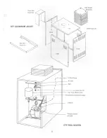
Boiler body with combustion chamber installed, theraltimeter, completely assembled and packaged with oil burner,
cadcell relay, pool & limit control, low water cutoff (OTF only), relief valve, indirect pool heating coil SC-150 (510/801)
SC-200 (1010/1600) with 1-1/2" I.P.S. tappings.

Selection of the right size OTF/ITF Heater

There are many factors related to proper sizing of Pool Heaters. We recommend you contact your installing dealer for
help in determining the correct size for your particular application.

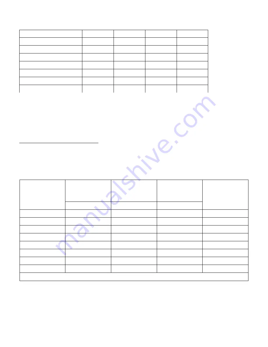
POOL HEATER SIZING CHART - HEAT LOSS FROM POOL SURFACE - BTUs PER HOUR

Desired

PoolTemperature
(°F)

Surface Area of Pool

Sq. Ft.

80°

85°

90°

Approximate

Gallons

500

137,000 Btu.

155,000 Btu.

200,000 Btu.

20,000

600

166,000 Btu.

185,000 Btu.

240,000 Btu.

24,000

700

200,000 Btu.

218,000 Btu.

280,000 Btu.

28,000

800

220,000 Btu.

250,000 Btu.

320,000 Btu.

32,000

900

248,000 Btu.

280,000 Btu.

360,000 Btu.

36,000

1000

275,000 Btu.

310,000 Btu.

400,000 Btu.

40,000

1200

330,000 Btu.

370,000 Btu.

480,000 Btu.

48,000

1400

384,000 Btu.

435,000 Btu.

560,000 Btu.

56,000

1600 or Larger: Refer inquiry to Thermo-Dynamics, Schuylkill Haven, PA 17972

NOTES: 1. These heat losses are based on an assumed wind velocity at the water surface of 5 m.p.h. and an ambient

temperature of 60°F.

2. Where surface area and gallons do not coincide, surface area must take precedence.

Summary of Contents for THERMOTRON ITF

Page 1: ...ynamics R O U T E6 1 P O B O X3 2 5 S C H U Y L K I L L H A V E N P A1 7 9 7 2 5 7 0 3 8 5 0 7 3 1 F A X 5 7 0 3 8 5 5 3 0 4 www thermodynamicsboiler com Operation Maintenance and Installation Instructions Models OTF ITF ...

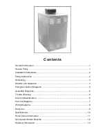
Page 2: ...ructions 2 Winterizing 3 Start Up and Operation 3 Piping Connection Diagrams 4 Assembly Diagrams 5 Trouble Shooting 6 Care and Maintenance 6 Pool Coil Diagram 7 Wiring Diagrams 8 Parts List 9 Specifications 10 Home Owner Information 11 Set Up and Service Records 12 Warranty Information 12 ...

Page 3: ...your appliance must be performed by a qualified heating technician You should utilize a qualified heat ing technician familiar with your installation to manage your heater and perform periodic mainte nance Proper care and maintenance of your pool heater will allow you to enjoy the benefits of your new purchase as well as extend its long useful life In the event that your serviceman encounters diff...

Page 4: ... flowrate may be set by comparing the temperature differ e n c eb e t w e e nt h e I n a n d O u t streams of the pool coil a Use full size piping and valve t o c o n n e c t t h e I n a n d O u t s t r e a m s of the pool coil b Allow the boiler to fire contin uously for a period of ten 10 to fif teen 15 minutes c With the bypass valve wide open take temperature readings for the coil d Note surfa...

Page 5: ...n burner power switch 9 Push the safety reset button on the primary control and release 10 Bleed the fuel unit on one pipe systems as soon as the burner motor starts To bleed attach a piece of 1 4 OD clear plastic tubing to the end of the bleed port Loosen same and purge oil of air for at least 15 sec onds after oil appears to be clear If oil stream does not become clear and free of air bubbles or...

Page 6: ......

Page 7: ......

Page 8: ... a Clogged nozzle b Dirty fan air handling parts c Improper burner adjustment refer to B Equipment Adjustment 5 Cycling On Off a Differential between pool setting and high limit too close b High limit setting too low c Remote pool sensing bulb in outlet water piping instead of inlet water piping Section IV Care and Maintenance 1 Heat Exchanger The tubular portions of the heat exchanger should be c...

Page 9: ...7 ...

Page 10: ......

Page 11: ...630 9 Air Tube Combination Pkg 510 801 675620 9 Air Tube Combination Pkg 901 1600 675640 10 Burner Flange Gasket 675170 11 Blank Air Band 510 801 675110 11 8 Hole Air Band 901 1600 675120 Cad Cell C 554 A 553024 Nozzle 2 50 x 80 Hollow 680246 Primary Control R7184B 553010 Coil Gasket 481000 Pool Controller L4031A 552035 SC 150 Coil 510 801 530060 Temperature and Altitude Gauge SC 200 Coil 901 1600...

Page 12: ...tors related to proper sizing of Pool Heaters We recommend you contact your installing dealer for help in determining the correct size for your particular application POOL HEATER SIZING CHART HEAT LOSS FROM POOL SURFACE BTUs PER HOUR Desired PoolTemperature F Surface Area of Pool Sq Ft 80 85 90 Approximate Gallons 500 137 000 Btu 155 000 Btu 200 000 Btu 20 000 600 166 000 Btu 185 000 Btu 240 000 B...

Page 13: ...y by a qualified service man If difficulty occurs the following should be observed before calling a service man a Check to be sure there is fuel in tank b Make sure power switch is turned on c Check to see if the desired pool setting is greater than the temperature of the pool WARNING EVEN THOUGH THE VENT CAP AREA IS APPROXIMATELY 40 INCHES ABOVE GROUND KEEP SMALL CHILDREN AWAY FROM YOUR POOL HEAT...

Page 14: ...wimming Pool Heater Warranty 5 Year Limited Swimming Pool Heaters boiler wet section are guaranteed for 5 years against defective material and work manship from the date of installation The indirect heat exchanger copper pool coil are guaranteed for 1 year against defective material and workmanship from the date of installation Controls and accessories made by others and attached to or furnished w...

Page 15: ...Part Number 595821 250 6 03 MIP 6426 ...

Reviews: