background image

14

WARNING

HAZARDOUS HIGH VOLTAGE CONDITIONS EXIST
INSIDE CONTROL PANEL. TURN "OFF" LINE
SWITCH ON FRONT PANEL AND UNPLUG LINE
CORD.

Remove all screws that fasten the cover.
Locate nylon connector J1 on the Interface
PCB Assembly. Depress both ears  on the
plug housing and gently pull out the connector.

With an Ohmmeter, measure the resistance
between TB1-4 (Orange wire) and TB1-6
(Red wire).

The proper heater resistance is 24 ohms. If
heater resistance is correct, then measure
between one heater lead (RED or ORANGE)
and incubator ground, it must be infinity
(Open). If the heater resistance check
indicates an open circuit, it may or may not
be open. In series with the heater is a thermal
overload switch. It might be that this thermal
overload is open and not the heater. To check
the heater and thermal switch directly, the
shelves of the incubator and the back wall
cover must be removed. Unplug heater and
measure its' resistance. If the resistance is
correct, check resistance between heater
terminal and the heater sheath. It must be an
open circuit. If the heater is good, then check
the thermal overload switch. At room
temperature it should be closed (0 ohms). This
switch should only open at 80°C and then
close at 65°C. If the heater and thermal switch
are good, then the problem is directed towards
the heater wires in the harness. If heater is
defective, contact White-Westinghouse for
replacement heater. See page 13.

3.

Malfunctioning Power Supply PCB assembly:

The Power Supply PCB Assembly has the
triac (solid state AC voltage switch) on it which
supplies the power to heater. This triac is "told"
to operate, when need be, by the
microprocessor.

Does not reach a high set point temperature:

No air circulation in chamber; inoperative fan
(see Remedy 1)

Low line voltage, less than 110V (see
Remedy 9)

RTD Temperature Probe (see Remedy 3,
Step D and/or Remedy 4).

Power Supply PCB Assembly (see Remedy
3)

Overcharged compressor (see Remedy 11)

Differences between Temperature Set and
Digital Temperature Readout: (see
performance figures, page 3)

RTD Temperature Probe (see Remedy 3,
Step D and/or Remedy 4).

Malfunctioning Power Supply PCB assembly
(see Remedy 3)

Takes an extremely long time to reach high
temperature set point:

No air circulation in chamber; inoperative fan
(see Remedy 1)

Low line voltage, less than 110V (see
Remedy 9)

Power Supply PCB assembly (see Remedy
3)

Overcharged Compressor (see Remedy 11)

Display indicates                  or

Malfunctioning RTD Temperature Probe
(Remedy 4)

POSSIBLE REMEDIES:

1.  Inoperative Fan:

Open the door. Place your hand near the grill
at the top rear of the chamber and check for
air circulation. If there is no air circulation, the
fan motor is malfunctioning. Contact White
Westinghouse for replacement part. See page
7.

2.

Burned-out heater:
To check this, the control panel cover must
be removed.

Summary of Contents for 3751

Page 1: ... Controlled Low Temperature Illuminated Incubator Model 818 3751 3752 Thermo Electron Corporation Millcreek Road Box 649 MArietta Ohio 45750 USA Phone 740 373 4763 Toll Free 800 848 3080 FAX 740 373 4189 ManualP N3177880 Rev F Dated 3 June 2005 ...

Page 2: ...N CORPORATION MAKES NO REPRESENTATIONS OR WARRANTIES WITH RESPECT TO THIS MANUAL IN NO EVENT SHALL THERMO BE LIABLEFORANYDAMAGES DIRECTORINCIDENTAL ARISINGOUTOFORRELATEDTO THE USE OF THIS MANUAL For repair information or replacement parts assistance from the manufacturer call Technical Services using our toll free telephone number 888 213 1790 FAX 740 373 4189 ...

Page 3: ...EVISION STATUS 6 99 B 8 99 Update part list for new kit s 20 C 9 01 Removed dual fans updated parts list 18 20 D 8 01 Updated performance data chart 2 E F 12 04 6 05 Update for base model FFU2064DW1 manual manufacturelocation 13 18 20 36100115 34001734 ...

Page 4: ... and Damage 1 General Information 2 Performance Data 2 Explanation of Controls 4 Instrumentation Port 6 Installation 6 Operation 7 Servicing 13 Troubleshooting 13 Maintenance 17 Wiring Diagrams 18 Parts Replacement List 20 Warranty 22 ...

Page 5: ......

Page 6: ...ndise was carefully packed and thoroughly inspected before leaving our factory Responsibility for safe delivery was assumed by the carrier upon acceptance of the shipment therefore claims for loss or damage sustained in transit must be made upon the carrier by the recipient as follows 1 Visible Loss or Damage Note any external evidence of loss or damage on the freight bill or express receipt and h...

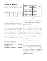
Page 7: ...ulating fan are used in conjunction with a microprocessor controlled proportioning circuit to achieve sensitive temperature control A RTD Resistance Temperature Detector located in the airstream senses any temperature deviation from the control point and heat is provided proportionally to maintain the desired temperature Regardless of what temperature is being maintained the compressor operates co...

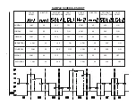
Page 8: ... PM 00 40 0 ON FRIDAY 2 AM 00 10 0 ON 4 PM 00 20 0 OFF SAMPLE SCHEDULE SHEET HOURS MINUTES SETPOINT LIGHT HOURS MINUTES SETPOINT LIGHT AM PM TEMPERATURE ON OFF AM PM TEMPERATURE ON OFF WEDNESDAY 4 AM 00 10 0 ON 6 PM 00 50 0 ON THURSDAY 3AM 00 50 0 OFF 5 PM 00 40 0 ON SATURDAY 1 AM 00 20 0 ON 3 PM 00 30 0 OFF ...

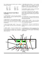
Page 9: ...LAY This four digit display indicates the incubator chamber temperature Also while programming it will display the value prompted by the time display 6 HEATER ON LAMP This lamp is illuminated when power is applied to the heater 7 HIGH LOW TEMPERATURE ALARM LAMPS These lamps will illuminate if the incubator s chamber temperature exceeds the high or low limit temperatures 8 LOCKED LAMP This lamp wil...

Page 10: ...xiliary panel which has the items shown in the figure on the next page They are described as follows 1 FUSE This fuse is in line with the main power cord that comes into the incubator The rating of this fuse is printed above the fuse holder The physical size of this fuse is 5 MM x 20 MM 2 ALARM RELAY This Alarm Relay output is provided to the user for the purpose of remotely monitoring the incubat...

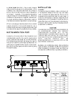
Page 11: ...ser s convenience Be sure to seal any gaps around the wire s going through the plug INSTALLATION Location To assure proper ventilation allow a minimum of 4 of clearance between the rear top and sides of the incubator and adjacent walls If two or more incubators are positioned side by side allow a minimum of 8 between cabinets Adjust the front leveling feet of the incubator so that the front is hig...

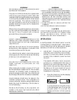
Page 12: ...ration of moisture within the chamber will only add frost and hasten the need for defrosting This chamber is not self defrosting Excessive frost buildup on the evaporator coil located on the lower rear wall will also affect temperature uniformity WARNING SAFETY PRECAUTIONS 1 DO NOT PLACE ANY EXPLOSIVE COMBUSTIBLE OR FLAMMABLE MATERIALS IN THE CHAMBER 2 DO NOT PLACE SEALED CONTAINERS IN THE CHAMBER...

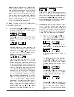
Page 13: ...he displays will go to those in Step D If the AM PM is incorrect use the or keys to select the proper one and then press ENTER D The displays will be similar to those below These are for the day selection If the day is correct press ENTER and the incubator will return to regular operation and the setting of the clock is complete If the day is incorrect use the or keys to select the day While using...

Page 14: ...n is displayed press the ENTER key and the displays will change to the following If PROG is displayed and you wish to change to CONT press the key and the displays will change to the following Now the user can select the SETPOINT temperature to operate at by means of the or and then pressing the ENTER key NOTE IF THE USER SELECTS THE CONTINUOUS MODE OF OPERATION AFTER BEING IN THE PROGRAM MODE THE...

Page 15: ...t this point the whole sequence starts over except that it is for Monday instead of Sunday If any of the selections are already what you desire for any day just press the ENTER key to advance to the next parameter While in the PROGRAM mode if you DO NOT press any keys for 10 seconds the incubator will automatically return to the normal operation mode 4 REPEAT KEY This is a convenience key for the ...

Page 16: ...trol to distinguish between door openings and real alarms The following is an example of this The incubator is controlling at 40 0 C and the low delay timer is set for 2 minutes and the alarm band is set for 1 degree Now the door is opened Most likely the temperature will begin to drop B Using the or keys select a numerical password of your choice C Press the ENTER key The LOCKED lamp will light a...

Page 17: ...or goes off it will be approximately 10 minutes before the compressor turns back on This is due to an internal time delay within the compressor The user can change this 20 minutes to a value they desire but once power is turned off and on again it will be 20 minutes again Use the or keys to select your time value and press ENTER The displays will change to the following This is the value for the a...

Page 18: ...ay failure see Remedy 12 No air circulation in chamber inoperative fan see Remedy 1 RTD Temperature Probe Location see Remedy 5 Ice buildup on evaporator coils see paragraph on Defrosting RTD Temperature probe see Remedy 3 Step D and or Remedy 4 Power Supply PCB Ass y see Remedy 3 Adjusting the Intake and Exhaust Ports The exhaust port is the top port on the door Open it slightly by turning it cou...

Page 19: ...he heater wires in the harness If heater is defective contact White Westinghouse for replacement heater See page 13 3 Malfunctioning Power Supply PCB assembly The Power Supply PCB Assembly has the triac solid state AC voltage switch on it which supplies the power to heater This triac is told to operate when need be by the microprocessor Does not reach a high set point temperature No air circulatio...

Page 20: ... as an Optoisolator which serves as the high low voltage isolator between the triac and the microprocessor When the incubator starts experiencing temperature problems and or variations due to known controller malfunctions these two components become prime suspects The reason being they are under higher operating stress than other components If the incubator starts experiencing temperature problems...

Page 21: ...bad when one of these displays appear check the connection of the probe to the circuit board 5 RTD Temperature Sensor Probe Location The Proper RTD location is important The RTD is supported by the stainless steel bracket attached on the rear wall and near the top of the chamber Two tube shaped clips securely support the RTD probe into place The RTD must be inserted fully into its support bracket ...

Page 22: ...when line voltages vary from nominal voltage by 5 or 10 Larger voltage variations may impair the Temperature Control Correct as required 10 Excessive ambient temperature variation If the incubator is placed close to the air conditioning outlet hot radiators or direct sunlight or if the ambient temperature changes drastically the chamber temperature will be affected Correct as necessary CAUTION THE...

Page 23: ...18 WIRING DIAGRAMS WIRING DIAGRAM 818 INCUBATOR 120V ...

Page 24: ...19 WIRING DIAGRAM 818 INCUBATOR 230V ...

Page 25: ...KIT 230V 3167217 CORD W PLUG 115V 3178031 HARNESS 815 818 115V 3177651 CORD W PLUG 230V 3176551 HARNESS 815 818 230V 3177652 FUSE KIT 5 AMP 230V 3167219 RS232 COMMUNICATIONS OPTION 3166245 THERMAL CUTOFF SWITCH 3175264 STOPPER KIT 3167215 BULB KIT 3167220 DOOR ASSEMBLY 3167017 DOOR GASKET 3174684 MOTOR FAN DUAL REAR MODEL MFU20F36W9 3174949 MOTOR FAN REAR MODEL FFU2064DW1 3185173 AUTO TRANSFORMER ...

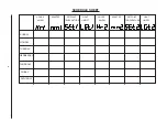
Page 26: ...21 SCHEDULE SHEET HOURS MINUTES SETPOINT LIGHT HOURS MINUTES SETPOINT LIGHT AM PM TEMPERATURE ON OFF AM PM TEMPERATURE ON OFF WEDNESDAY SATURDAY FRIDAY THURSDAY TUESDAY MONDAY SUNDAY ...

Page 27: ......

Page 28: ...l warranty period The Technical Services Department must give prior approval for return of any components or equipment At Thermo s option all non conforming parts must be returned to Thermo Electron Corporation postage paid and replacement parts are shipped FOB destination THIS WARRANTY IS EXCLUSIVE AND IN LIEU OF ALL OTHER WARRANTIES WHETHER WRITTEN ORAL OR IMPLIED NO WARRANTIES OF MERCHANTABILIT...

Page 29: ......

Reviews: