background image

Section 5: Maintenance

If the unit has been in service, turn it
off and disconnect the power cord
connector before proceeding with any
maintenance.

Before using any cleaning or decontamination
method except those recommended by the manu-
facturer, users should check with the manufactur-
er that the proposed method would not damage
the equipment.

5.1  Cleaning

The chamber interior may be cleaned with a general-use

laboratory disinfectant or alcohol.

The cabinet exterior may be cleaned with soap and water

or any non-abrasive commercial glass cleaner. The Thermopane
glass door may be cleaned with commercial glass cleaner or
with a solution of ammonia and water.

Alcohol, even a 70% solution, is volatile and
flammable. Use it only in a well ventilated area
that is free from open flame. If any component is
cleaned with alcohol, do not expose the compo-
nent to open flame or other possible hazard.    

Do not use strong alkaline or caustic agents.
Stainless steel is corrosion resistant, not corrosion
proof. Do not use solutions of sodium hypochlorite
(bleach) as they may cause pitting and rust.

5.2  Cleaning the Glass Doors

The chamber glass door and the optional independent inner

doors may be cleaned using the same disinfectant as used on
the incubator interior. It is imperative that they be rinsed with
sterile distilled water to remove the disinfectant residue. The
doors should then be dried with a sterile soft cloth.

Some precautions in the cleaning and care of the incubator
glass doors:

Moisture leaches alkaline materials (sodium, Na) from the

surface of the glass. Evaporation of the moisture concentrates
the alkaline and may produce a white staining or clouding of
the glass surface. Cleaning chemicals with a PH above 9 accel-
erate the corrosion process. Therefore, it is very important to
rinse and dry the glass doors after cleaning.

There is no simple method for repairing corroded glass. In

most cases, the glass must be replaced.

5.3  Cleaning the Humidity Reservoir

Periodic cleaning of the humidity reservoir beneath the

incubator floor is recommended in order to remove bacteria,
fungi or any accumulated mineral deposits. 

1. Turn off and/or disconnect the water supply to the

humidity reservoir.

2. Attach a drain fitting and hose to the drain port on the

back of the unit. Run the hose to an appropriate drain.

3. With an adjustable wrench, remove the brass overflow

fitting located at the rear of the humidity reservoir.
Allow reservoir to drain. Reservoir holds approximately
4 gallons (15.4 L).

4. Disassemble the hose bracket from the incubator floor. 
5. Remove the 8 screws securing the floor. Using the circu-

lar black plastic grommet, slide the floor outward to
expose the humidity reservoir.

6. Remove any remaining water and sediment from the

reservoir with a clean sponge. 

7. Clean the reservoir with a general-use laboratory disin-

fectant. Rinse well with sterile distilled water and wipe
dry with a clean cloth.

Note:

On reassembly, the brass overflow fitting must be

checked for leaks.

Distilled water used in the incubator humidifier

reservoir must be within the 50K Ohm to 1M Ohm
range to protect and prolong the life of the stain-
less steel unit.
Use of tap water or distilled water outside the
specified range will decrease the operating life of
the unit and may void the warranty.   

Do not use strong alkaline or caustic agents.

Stainless steel is corrosion resistant, not corrosion
proof. Do not use solutions of sodium hypochlorite
(bleach) as they may cause pitting and rust.

Model 3950/3951 _____________________________________________________________________________Maintenance

5 - 1

Summary of Contents for 3950

Page 1: ...Models 3950 and 3951 29 cu ft Capacity Forma Reach In CO2 Incubator Operating and Maintenance Manual Manual No 7003950 Rev 7 ...

Page 2: ...03 Removed note about shipping tape on screws of sidewalls ccs 20959 IN 3048 10 1 02 Added spacers to power supply mounting ccs 7 20841 IN 3038 7 10 02 Updated 3950 electrical schematic from 285758 to 460038 GFI outlet ccs 20883 IN 3034 6 12 02 Clarified p trap alignment on page 1 3 ccs 20651 IN 3019 2 26 02 Updated 1900008 06 1 to rev 5 chg in control panel mounting hardware ccs 6 19617 12 18 00 ...

Page 3: ...ocedimientos asociadas con este simbulo Equipment being maintained or serviced must be turned off and locked off to prevent possible injury Risques potentiels liés à l énergie L équipement en entretien ou en maintenance doit être éteint et mis sous clé pour éviter des blessures possibles Geräte an denen Wartungs oder Servicearbeiten durchgeführt werden müssen abgeschaltet und abgeschlossen wer den...

Page 4: ...Model 3950 3951 _______________________________________________________________________________________ iii ...

Page 5: ...Low CO2 Alarm Limit tracking alarm 3 2 g Setting High CO2 Alarm Limit tracking alarm 3 2 h Enabling CO2 Alarms to Trip Relay Contacts 3 2 i Setting New Zero Number for New CO2 Sensors 3 2 j Setting New Span Number for CO2 Sensors 3 2 k Enabling the High Humidity Feature 3 2 l Selecting a Primary Tank w Gas Guard Option 3 3 m Enabling the Gas Guard System 3 3 n Setting RS485 Communications Address ...

Page 6: ...3950 3951 ____________________________________________________________________Installation and Start Up Section 1 Installation and Start Up 1 1 Figure 1 1 Front View Figure 1 2 Back View Figure 1 3 Side View ...

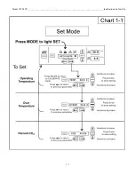
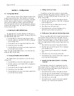
Page 7: ...In Incubator has four basic modes that allow incubator setup Run Setpoints Calibration and System Configuration Run is the default mode during normal operation Set is used to enter system setpoints Calibration is used to calibrate various system parameters Configuration allows for custom setup of various options The chart below shows the selections under each of the modes Scroll for Parameters Arr...

Page 8: ...n or inside this unit are the responsibility of the user c Installing the Shelves The shelves may be installed at any level in the incubator Install a shelf channel on each side With the tabs point ing up attach the channel by locating the rivet into a slotted hole far end first Pull the channel toward the front and slide the front rivet on the channel into the slotted hole and press down Make sur...

Page 9: ...se water supply Connect a low pressure not more than 30 PSI water line equipped with a manual shut off valve to the inlet fitting on the float valve reservoir The 1 4 hose connection is located on the rear of the incubator cabinet With the water turned on a float valve inside the incubator regulates the water level in the humidity reservoir When the reservoir is full a 10 second audible tone is he...

Page 10: ...facility safety officer to ensure that the equipment is installed in accordance with the codes and regulations that are applicable in your area The CO2 gas supply being connected should be industrial grade 99 5 pure and should not contain siphon tubes Install a two stage pressure regulator at the cylinder outlet The high pressure gauge at the tank should have 0 2000 psig range The low pressure gau...

Page 11: ... X is displayed in the message center 3 Press the up or down arrow until the desired Otemp set point is displayed 4 Press Enter to save the setting 5 Press the Mode key until the Run indicator lights or press the right or left arrow to go to the next or previous parameter c Setting the CO2 Setpoint All CO2 cells are calibrated at the factory at 37 C medium humidity and 10 CO2 Therefore if a temper...

Page 12: ...Model 3950 3951 ____________________________________________________________________Installation and Start Up 1 7 ...

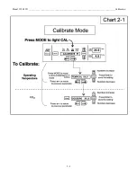
Page 13: ...Press the right arrow until TEMPCAL XX X appears in the message center 3 Press the up down arrow to match the display to the cal ibrated instrument 4 Press Enter to store calibration 5 Press the Mode key to return to Run or the right left arrow to go to next previous parameter b Calibrating the CO2 System Model 3950 Series incubators have a CO2 sensor The incu bator atmosphere is not only effected...

Page 14: ...Model 3950 3951 _____________________________________________________________________________Calibration 2 2 ...

Page 15: ...ng the setpoints calibration or con figuration A setting of 000 will bypass the access code The factory setting is 000 1 Press the Mode key until the Config indicator lights 2 Press the right arrow until Acc Code XXX is displayed in the message center 3 Press up or down arrow to change the access code 4 Press Enter to save the access code 5 Press the Mode key to return to the Run mode or right lef...

Page 16: ... new CO2 sensor is being installed the two numbers on the factory installed sticker on the cell must be entered to cali brate the CO2 in the unit Note For the technician s convenience a label containing the two numbers on the cell is affixed inside the electronics drawer 1 Press the Mode key until the Config indicator lights 2 Press the right arrow until Z XXXX is displayed in the message center 3...

Page 17: ...e center 3 Press up down arrow to toggle the setting ON OFF 4 Press Enter to save the setting 5 Press the Mode key to return to Run mode or right left to go to next previous parameter n Setting RS485 Communications Address 1535 compatible only On units that have the RS485 option direct communication with the Model 1535 alarm system can be established Each piece of equipment connected to the 1535 m...

Page 18: ...Model 3950 3951 _____________________________________________________________________________Configuration 3 4 ...

Page 19: ...Model 3950 3951 _____________________________________________________________________________Configuration 3 5 ...

Page 20: ... alarms are disabled when the CO2 set point is 0 0 Model 3950 3951 _________________________________________________________________________________Alarms 4 1 4 2 Sensor Fault Alarms The microprocessor in 3950 Series incubators continually scans all available sensors to ensure that they are operating properly Should an error be detected the incubator will sound an alarm and display the appropriate...

Page 21: ...y a qualified service technician The following is a condensed list of preventive maintenance requirements See the specified section of the instruction manual for further details We have qualified service technicians using NIST traceable instruments available in many areas For more information on Preventive Maintenance or Extended Warranties please contact us at the number listed below Cleaning and...

Page 22: ... 1 Verify and document CO2 and temperature calibration 9 1 4b 5 3 Perform a complete decontamination procedure Wipe down interior shelves and side panels with disinfectant Drain water reservoir and wipe down with disinfectant Rinse everything well with sterile distilled water Between experiments More frequent decontamination may be required depending on use and environmental conditions Figure 6 5 ...

Page 23: ... chemicals with a PH above 9 accel erate the corrosion process Therefore it is very important to rinse and dry the glass doors after cleaning There is no simple method for repairing corroded glass In most cases the glass must be replaced 5 3 Cleaning the Humidity Reservoir Periodic cleaning of the humidity reservoir beneath the incubator floor is recommended in order to remove bacteria fungi or an...

Page 24: ...e If the fuse s blow after restoring power to the incubator con tact the Technical Services Department at the telephone number on the back cover of this instruction manual 5 5 Discarding or Taking the Incubator out of Service Federal regulations require that doors be removed from incubators before units are taken out of serv ice or discarded Model 3950 3951 ________________________________________...

Page 25: ...this manual Configuration Mode Figure 6 2 c Connecting the Analog Output Boards 190512 190543 190544 The electronics section contains haz ardous voltages Only qualified elec trical service personnel should access this area The analog output board is an option that allows the incu bator to output analog signals representing the air temperature and CO2 content of the incubator interior There are thr...

Page 26: ... inlets for the Gas Guard are located on the back of the unit Using 1 4 ID tubing connect one of the CO2 sup ply tanks to the fitting labeled CO2 Inlet 1 Tank Connect the second CO2 supply tank to the fitting labeled CO2 Inlet 2 Tank Install 3 8 hose clamps to secure the 1 4 ID tubing to the fit tings Refer to Figure 6 6 b Activating the Gas Guard The built in Gas Guard is not turned on when shipp...

Page 27: ...t is 50 pounds Shakers must not exceed 250 rpm when used inside this incubator For shaker power connection an internal outlet in the upper right corner of the back wall is installed Casters are installed at the factory for moving the cabinet to the desired location After the unit is in place and prior to operation the casters must be removed The large rubber vibration feet factory installed are po...

Page 28: ...0 F B 96 5 cm x 203 2 cm x 83 8 cm Interior 31 0 W x 60 0 H x 27 0 F B 78 7 cm x 152 4 cm x 68 6 cm Weight 500 lbs 226 8 kg Accessories CI Customer Install FI Factory Install 224139 Stainless steel shelf channels CI 224155 Perforated shelf kit CI 190239 Lexan inner door kit FI 190591 Door cover FI 190892 Door cover CI 190164 Thru wall access port FI 500182 Reinforced floor with ramp to accommodate...

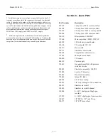
Page 29: ...s dust occurs with the exception of occasional conductivity caused by condensation Section 8 Spare Parts Part Number Description 230135 1 amp fuse 3950 accessory outlet 230158 2 5 amp fuse 3950 interior outlet 230120 0 5 amp fuse 3951 accessory outlet 230106 1 5 amp fuse 3951 interior outlet 156112 Blower motor 1 30th HP 170164 Motor capacitor 3 MFD 370VAC 600210 300 watt wire wound heater 250118 ...

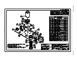
Page 30: ...Model 3950 3951 ______________________________________________________________________________Spare Parts 8 2 ...

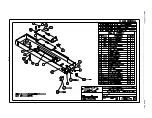
Page 31: ...Model 3950 3951 ______________________________________________________________________________Spare Parts 8 3 ...

Page 32: ...Model 3950 3951 ______________________________________________________________________________Spare Parts 8 4 ...

Page 33: ...Model 3950 3951 ______________________________________________________________________________Spare Parts 8 5 ...

Page 34: ...Model 3950 3951 ______________________________________________________________________________Spare Parts 8 6 ...

Page 35: ...Model 3950 3951 ______________________________________________________________________________Spare Parts 8 7 ...

Page 36: ...Model 3950 3951 ______________________________________________________________________________Spare Parts 8 8 ...

Page 37: ...Model 3950 3951 ______________________________________________________________________________Spare Parts 8 9 ...

Page 38: ...Model 3950 3951 ______________________________________________________________________________Spare Parts 8 10 ...

Page 39: ...Model 3950 3951 ______________________________________________________________________Electrical Schematics 9 1 ...

Page 40: ...Model 3950 3951 ______________________________________________________________________Electrical Schematics 9 2 ...

Page 41: ...Model 3950 3951 ______________________________________________________________________Electrical Schematics 9 3 ...

Page 42: ...Model 3950 3951 ______________________________________________________________________Electrical Schematics 9 4 ...

Page 43: ...Thermo Electron Corporation Controlled Environment Equipment Millcreek Road P O Box 649 Marietta Ohio 45750 U S A Telephone 740 373 4763 Telefax 740 373 4189 ...

Reviews: