background image

Chapter 3  Operation 

3-64 


Pressure


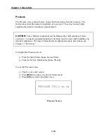
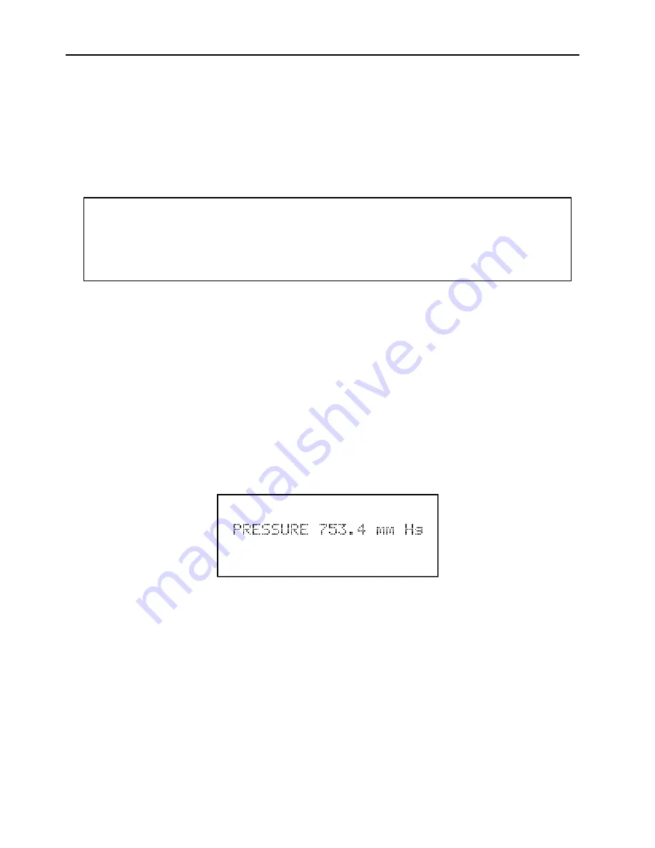
The Pressure screen, shown below, shows the fluorescence chamber pressure.  The 
fluorescence chamber pressure is updated every second.  This screen is used while 
adjusting the pressure transducer potentiometers. 


CAUTION:

  Some internal components can be damaged by small amounts of static 

electricity.  A properly grounded antistatic wrist strap must be worn while handling any 
internal component.  For more information about appropriate safety precautions, see 
Chapter 7, “Servicing.” 


To display the Pressure screen: 


From the Main Menu choose Service Mode 


From the Service Mode menu choose Pressure 


To use the Pressure screen: 


This is a view only screen 


Press

 MENU

 to return to the Service Mode menu  


Press

 RUN

 to return to the Run screen  


Pressure Screen 


Summary of Contents for 48C

Page 1: ...HERMO ELECTRON CORPORATION ENVIRONMENTAL INSTRUMENTS 27 FORGE PARKWAY FRANKLIN MASSACHUSETTS 02038 866 282 0430 Toll Free 508 520 0430 International 508 520 1460 Fax www thermo com eid 3Mar2004 The 220V option complies with 89 336 EEC directive for electromagnetic compatibility ...

Page 2: ...yze Detect Measure Control are trademarks of Thermo Electron Corporation All other product names and logos are the property of their respective owner Specifications terms and pricing are subject to change Not all products are available in all countries Please consult your local sales representative for details ...

Page 3: ...quirements when operated with the following Range 0 1 to 100 ppm Averaging Time 10 to 300 seconds Temperature Range 20 to 30 C Line Voltage 90 to 110 VAC 50 60 Hertz 105 to 125 VAC 50 60 Hertz 210 to 250 VAC 50 60 Hertz Pressure Compensation on or off Temperature Compensation on or off Flow Rate 0 5 to 2 LPM RS 232 Interface With or without the following options 100 Teflon Particulate Filter 200 C...

Page 4: ......

Page 5: ...hbutton 3 1 Menu Pushbutton 3 2 Enter Pushbutton 3 2 Help Pushbutton 3 2 Pushbuttons 3 2 Software Overview 3 2 Power Up Screen 3 4 Self Test Screen 3 4 Run Screen 3 5 Main Menu 3 5 Range Menu 3 6 Single Range Mode 3 7 Dual Range Mode 3 7 Autorange Mode 3 8 Gas Units 3 10 CO Range 3 11 Custom Ranges Menu 3 13 Custom Range Screen 3 14 Averaging Time 3 15 Calibration Factors Menu 3 16 CO Background C...

Page 6: ... Ratio 3 39 AGC Intensity 3 40 Motor Speed 3 41 Test Analog Outputs 3 42 Zero 3 43 Fullscale 3 44 Ramp 3 45 Option Switches 3 46 Alarms 3 47 Internal Temperature 3 48 Min and Max Internal Temperature Limits 3 49 Chamber Temperature 3 50 Min and Max Chamber Temperature Limits 3 51 Pressure 3 52 Min and Max Pressure Limits 3 53 Flow 3 54 Min and Max Flow Limits 3 55 Bias Voltage 3 56 Min and Max Bia...

Page 7: ...3 78 CHAPTER 4 CALIBRATION 4 1 Equipment Required 4 1 CO Concentration Standard 4 1 Zero Air Generator 4 1 Compression 4 2 Drying 4 2 Oxidation 4 2 Scrubbing 4 2 Flow Meter s and Controller s 4 2 Pressure Regulator for CO Standard Cylinder 4 3 Mixing Chamber 4 3 Output Manifold 4 3 Pre Calibration 4 3 Calibration 4 3 Connect Instrument 4 3 Zero Adjust 4 4 Span Adjust 4 4 Additional Concentration S...

Page 8: ...r Replacement 7 6 Optical Bench Replacement 7 6 Optical Switch Replacement 7 7 Bench Heater and Bench Heater Power Supply Replacement 7 7 Preamplifier Detector Assembly Replacement 7 8 Pump Rebuilding 7 8 Pump Replacement 7 9 Pressure Transducer Replacement 7 10 Flow Sensor Replacement 7 10 Input Signal Conditioning Board Replacement 7 11 DC and Bias Power Supply Boards Replacement 7 11 Capillary ...

Page 9: ...assemblies 8 5 Optical Bench 8 5 Correlation Wheel and Chopper Motor 8 5 Infrared IR Source 8 5 Flow Components 8 6 Temperature and Pressure Transducer 8 6 CHAPTER 9 OPTIONAL EQUIPMENT 9 1 Rack Mounts with Slides 9 1 Internal Zero Span and Sample Solenoid Valves 9 3 Zero Span Check 9 3 Remote Activation of Zero Span and Sample Valves 9 6 Input Pins 9 7 Instrument Status Outputs 9 7 4 20 mA Isolate...

Page 10: ...nalog Digital Board C 5 Digital Analog Board C 6 Power Supply Board C 7 Preamplifier C 8 Input Board C 9 Bias Power Supply Board C 10 Temperature Control Board C 11 C Link Board C 12 4 20 mA Outputs optional C 13 Input Output Board optional C 14 Rear Connector Interface Board C 15 APPENDIX D PUMP MAINTENANCE D 1 ...

Page 11: ...Panel Terminal Strip in Autorange Mode 3 8 3 6 Analog Output in Autorange Mode 3 9 3 7 Location of Internal Option Switches 3 76 4 1 Calibration Flow schematic 4 4 7 1 Properly Grounded Antistatic Wrist Strap 7 1 7 2 Model 48C Component Layout 7 3 7 3 Optical Bench Exploded View 7 5 7 4 Optical Bench 7 7 7 5 Pump Assembly Diagram 7 10 9 1 Rack Mount Option Assembly 9 1 9 2 Model 48C Dimensional Ou...

Page 12: ......

Page 13: ...onverters 3 67 3 3 Option Switch Functions 3 77 3 4 Operating Mode Truth Table 3 78 4 1 Scrubbing Materials 4 2 5 1 Recommended Spare Parts 5 1 7 1 Replacement Parts 7 2 9 1 Instrument Status Output Truth Table 9 9 9 2 Current Output Channel with Corresponding Concentration 9 9 ...

Page 14: ......

Page 15: ...ailable for assistance with any questions or problems that may arise in the use of this analyzer PRINCIPLE OF OPERATION The Model 48C is based on the principle that carbon monoxide CO absorbs infrared radiation at a wavelength of 4 6 microns Because infrared absorption is a non linear measurement technique it is necessary for the instrument electronics to transform the basic analyzer signal into a...

Page 16: ...n the cell The chopped detector signal is modulated by the alternation between the two gas filters with an amplitude related to the concentration of CO in the sample cell Other gases do not cause modulation of the detector signal since they absorb the reference and measure beams equally Thus the GFC system responds specifically to CO The Model 48C outputs the CO concentration to the front panel di...

Page 17: ...o drift 24 hour 0 1 ppm Span drift 24 hour 1 fullscale Response time 60 seconds 30 second time setting Precision 0 1 ppm Linearity 1 fullscale 1000 ppm 2 5 fullscale 1000 ppm Sample flow rate 0 5 2 liters min Operating temperature 20 30 C may be safely operated over the range of 0 45 C Power requirements 105 125 VAC 60 Hz 220 240 VAC 50 Hz 100 Watts Physical dimensions 16 75 W X 8 62 H X 23 D Weig...

Page 18: ......

Page 19: ...on receipt of the analyzer there is obvious damage to the shipping container notify the carrier immediately and hold for inspection The carrier and not Thermo Environmental Instruments Inc is responsible for any damage incurred during shipment Follow the procedure below to unpack and inspect the instrument 1 Remove the instrument from the shipping container and set on a table or bench that allows ...

Page 20: ...ne 3 If the optional zero span solenoid valves are installed connect a source of CO free air to the ZERO bulkhead 4 If the optional zero span solenoid valves are installed connect a source of CO span gas to the SPAN bulkhead 5 Connect a suitable recording device to the rear panel terminals Refer to Operating Modes in Chapter 3 for the pin out of the rear panel terminals in each operating mode 4 Pl...

Page 21: ...Chapter 2 Installation Figure 2 1 Model 48C Rear Panel 42P730 Figure 2 2 Atmospheric Dump Bypass Plumbing 57P7100 2 3 ...

Page 22: ... 52C 20 2 Alpha 5162C 18 2 Alpha 1743C 20 4 Alpha 1747 4C 18 4 Alpha 5320 4C 20 4 Alpha 5154C 20 4 Alpha 5164C 18 4 Belden 8208 18 2 Maximum shielding Under harsh environments maximum shielding may be required The following tools are required Small screwdriver Wire stripper Electrical tape or heat shrink tubing The user supplied shielded analog output cable must be properly grounded by coming into...

Page 23: ... the shielded cable through the cable clamp on the analog output cover as shown in Figure 2 4 Figure 2 4 Exploded View of Analog Output Cover Installation 2 Insert the bare signal wire into the slot of the header 3 Tighten down the corresponding set screw 4 Repeat steps 2 and 3 for each signal wire 5 Plug the header s into the analog output connectors 6 Install the analog output cover using the fo...

Page 24: ... assembly Part No Description Qty 7592 Analog output cover 1 11519 8 Position header 2 5889 6 Star lock washers 4 5820 6 32X3 8 screw 4 14549 Cable clamp 1 STARTUP 1 Turn the power on 2 Set instrument parameters such as operating ranges and averaging times to appropriate settings For more information about instrument parameters see Chapter 3 Operation 3 Before beginning actual monitoring perform a...

Page 25: ...e items than can be displayed at one time For these menus use the and pushbuttons to move the cursor up and down to each choice PUSHBUTTONS Run Pushbutton The RUN pushbutton shown below is used to display the Run screen The Run screen displays the CO concentration In addition the RUN pushbutton is used to switch the optional zero span and sample solenoid valves For more information about the optio...

Page 26: ...a help screen press MENU to return to the previous screen or RUN to return to the Run screen Pushbuttons The four arrow pushbuttons and move the cursor up down right and left SOFTWARE OVERVIEW The Model 48C is based on menu driven software as illustrated by the flowchart in Figure 3 2 The Power Up and Self Test screens shown at the top of the flowchart are displayed each time the instrument is tur...

Page 27: ...Chapter 3 Operation 3 3 Figure 3 2 Flowchart of Menu Driven Software ...

Page 28: ...d on power up of the Model 48C Power Up Screen Self Test Screen The Self Test Screen as shown below is displayed while the internal components are warming up and a diagnostic check is performed Self Test Screen MODEL 48C SELF TEST 12 05 94 11 30 THERMO ENVIRONMENTAL INSTRUMENTS MODEL 48C ...

Page 29: ...ange producing the low range concentration and the other uses the coefficients associated with the high range producing the high range concentration The l preceding CO PPM indicates that the low concentration is displayed To display the high concentration press the pushbutton To display the low concentration press the pushbutton Run Screen Main Menu The Main Menu contains several submenus as shown...

Page 30: ...right hand corner For more information about the single dual or autorange modes see Single Range Mode Dual Range Mode and Autorange Mode below The AutoRange screen is the same as the Dual screen below except has AUTO where the Dual screen reads DUAL To display the Range menu From the Main Menu choose Range To use the Range menu Press the and pushbuttons to move the cursor to each choice Press ENTE...

Page 31: ...To use the single range mode set option switches 4 and 5 off For more information about setting the internal option switches see Internal Option Switches later in this chapter 42P942 2 Figure 3 3 Pin Out of Rear Panel Terminal Strip in Single Range Mode Dual Range Mode In dual range mode there are two independent CO analog outputs as shown below 42P943 3 Figure 3 4 Pin Out of Rear Panel Terminal S...

Page 32: ...The high and low ranges are defined in the Range menu The CO analog output has a corresponding status output as shown in Figure 3 5 The status outputs are used to indicate which range high or low is being used 42P943 1 Figure 3 5 Pin Out of Rear Panel Terminal Strip in Autorange Mode For example suppose the low CO range is set to 50 ppm and the high CO range is set to 100 ppm see Figure 3 6 Sample...

Page 33: ...tches later in this chapter When the high CO range is active the concentration must drop to 95 of the low CO range for the low CO range to become active To use the autorange mode set option switch 4 and 5 on For more information about setting the internal option switches see Internal Option Switches later in this chapter 42P942 5 Figure 3 6 Analog Output in Autorange Mode ...

Page 34: ...o the highest range in that mode For example when switching from mg m 3 to ppm all the ranges default to 10 000 ppm The first line of the display shows the current gas units The second line of the display is where the gas units are selected To display the Gas Units screen From the Main Menu choose Range From the Range Menu choose Gas Units To use the Gas Units screen Use the and pushbuttons to sel...

Page 35: ... first line to indicate which range is displayed For more information about the single dual or autorange modes see Single Range Mode Dual Range Mode and Autorange Mode earlier in this chapter Table 3 1 lists the available preset ranges To display the CO range screen From the Main Menu choose Range If in Dual or Auto Range from the Range menu choose CO Hi Range or CO Lo Range To use the CO ranges U...

Page 36: ... 10 10 20 20 50 50 100 100 200 200 500 500 1 000 1 000 2 000 2 000 5 000 5 000 10 000 10 000 C1 C1 C2 C2 C3 C3 Table 3 1 Available Operating Ranges C1 C2 and C3 are custom ranges For more information about custom ranges see Custom Ranges Menu below ...

Page 37: ...0 000 mg m 3 can be specified See Custom Range Screen below for more information about defining the custom ranges To display the Set Custom Ranges screen From the Main Menu choose Range From the Range menu choose Set Custom Ranges To use the Set Custom Ranges menu Use the and pushbutton to move the cursor between each custom range Press ENTER to select the custom range to define Press MENU to retu...

Page 38: ...e screen See CO Range above for more information To display the Custom Range screen From the Main Menu choose Range From the Range menu choose Set Custom Ranges From the Set Custom Range menu choose C1 C2 or C3 To use the Custom Range screen Use the and pushbutton to increment and decrement each digit Use the and pushbutton to move the cursor left and right Press ENTER to accept the custom range P...

Page 39: ...e typically used to smooth output data The Averaging Time screens for the single and dual or auto range modes are shown below In the dual and auto range modes an Averaging Time Menu is displayed before the averaging time screens This menu is needed because the dual and auto range modes have two averaging times high and low The Averaging Time screens function the same way in the single dual and aut...

Page 40: ...an be calibrated manually using this menu by changing the factors To display the Calibration Factors menu From the Main Menu choose Calibration Factors To use the Calibration Factors menu Use the and pushbuttons to move the cursor up and down Press ENTER to go to the Calibration Factor screen Press MENU to return to the Main Menu Press RUN to return to the Run Screen LO SPAN GAS 1 000 LO CO COEF 1...

Page 41: ...O reading In the example below the analyzer is reading 1 4 ppm of CO while sampling zero air The CO background correction is 0 0 ppm That is the analyzer is not applying a zero background correction The question mark is used as a prompt to change the background correction In this case the background correction must be increased to 1 4 ppm in order for the CO reading to be at 0 ppb To set the CO re...

Page 42: ...tors From the Calibration Factors menu choose CO Background To use the CO Background screen Use the and pushbuttons to increment decrement the CO background Press ENTER to accept a change in the background Press MENU to return to the Calibration Factors menu Press RUN to return to the Run screen CO Background Screen ...

Page 43: ...rs menu choose Span Gas To use the CO Span Gas screen Use the and pushbuttons to increment decrement the gas value Use the and pushbuttons to change the gas value Press ENTER to accept a change Press MENU to return to the Calibration Factors menu Press RUN to return to the Run screen Single and Dual Auto range CO Span Gas Screen SPAN GAS PPM 00000 250 SET TO 00000 500 78 INC DEC HI SPAN GAS PPM 00...

Page 44: ...d is being used to correct the CO concentration Notice that as the span coefficient value is changed using the and pushbuttons the current CO concentration reading on the first line also changes To display the CO Span Coefficient screen From the Main Menu choose Calibration Factors From the Calibration Factors menu choose CO Coef To use the CO Span Coefficient screen Use the and pushbuttons to inc...

Page 45: ...necessary if the two ranges used are not close to one another for example a low CO range of 50 ppm and a high CO range of 1000 ppm For more information about calibration see Chapter 4 Calibration To display the Calibration menu From the Main Menu choose Calibration To use the Calibration menu Use the and pushbuttons to move the cursor up and down Press ENTER to accept the choice Press MENU to retu...

Page 46: ... the current CO reading For more information about the CO background see CO Background Correction earlier in this chapter To display the Calibrate Zero screen From the Main Menu choose Calibration From the Calibration menu choose Calibrate Zero To use the Calibrate Zero screen Press ENTER to set the CO reading to zero Press MENU to return to the Calibration menu Press RUN to return to the Run scre...

Page 47: ...nt CO reading For more information about calibration see Chapter 4 Calibration To display the Calibrate CO screen From the Main Menu choose Calibration From the Calibration menu choose Calibrate CO To use the Calibrate CO screen Use the and pushbuttons to increment decrement each digit Use the and pushbuttons to move the cursor left and right Press ENTER to calibrate the CO reading to the CO calib...

Page 48: ...is menu contains items that control general instrument operations To display the Instrument Controls Menu From the Main Menu choose Instrument Controls To use the Instrument Controls Menu Use the and pushbuttons to scroll through the choices Press ENTER to select a choice Instrument Controls Menu ...

Page 49: ...s shown below When temperature correction is on the first line of the display shows the current internal instrument temperature When temperature correction is off the first line of the display shows the standard temperature of 25 o C To display the Temperature Correction screen From the Main Menu choose Instrument Controls From the Instrument Controls menu choose Temperature Correction To use the ...

Page 50: ... shown below When pressure correction is on the first line of the display represents the current pressure in the reaction chamber When pressure correction is off the first line of the display shows the standard pressure of 750 mm Hg To display the Pressure Correction screen From the Main Menu choose Instrument Controls From the Instrument Controls menu choose Pressure Correction To use the Pressur...

Page 51: ...e Baud Rate screen From the Main Menu choose Instrument Controls From the Instrument Controls menu choose Baud Rate To use the Baud Rate screen Use the and pushbuttons to increment decrement the baud rate Press ENTER to accept a change Press MENU to return to the Instrument Controls menu Press RUN to return to the Run screen Baud Rate Screen BAUD RATE 9600 SET TO 2400 78 INC DEC ...

Page 52: ...ault Instrument ID of 48 For more information about the Instrument ID see Appendix B RS 232 Commands To display the Instrument ID screen From the Main Menu choose Instrument Controls From the Instrument Controls menu choose Instrument ID To use the Instrument ID screen Use the and pushbuttons to increment decrement the ID number Press ENTER to accept a change Press MENU to return to the Instrument...

Page 53: ... extend the life of the display To display the Screen Brightness screen From the Main Menu choose Instrument Controls From the Instrument Controls menu choose Screen Brightness To use the Screen Brightness screen Use the and pushbuttons to increment decrement the screen brightness Press ENTER to accept a change Press MENU to return to the Instrument Controls menu Press RUN to return to the Run scr...

Page 54: ...the Model 48C For more information about the service mode see Service Mode Menu later in this chapter To display the Service Mode screen From the Main Menu choose Instrument Controls From the Instrument Controls menu choose Service Mode To use the Service Mode screen Press ENTER to toggle service mode on and off Press MENU to return to the Instrument Controls menu Press RUN to return to the Run sc...

Page 55: ...strument power is off To display the Time screen From the Main Menu choose Instrument Controls From the Instrument Controls menu choose Time To use the Time screen Use the and pushbuttons to increment decrement the hours and minutes Use the and pushbuttons to move the cursor left and right Press ENTER to accept a change Press MENU to return to the Instrument Controls menu Press RUN to return to th...

Page 56: ...y the Date screen From the Main Menu choose Instrument Controls From the Instrument Controls menu choose Date To use the Date screen Use the and pushbuttons to increment decrement the month day and year Use the and pushbutton to move the cursor left and right Press ENTER to accept a change Press MENU to return to the Instrument Controls menu Press RUN to return to the Run screen Date Screen DATE 1...

Page 57: ...on and functions This menu is useful when troubleshooting the instrument To display the Diagnostics menu From the Main Menu choose Diagnostics To use the Diagnostics menu Use the and pushbuttons move the cursor up and down Press MENU to return to the Main Menu Press RUN to return to the Run screen Diagnostics Menu ...

Page 58: ... the instrument please note the program numbers To display the Program Number screen From the Main Menu choose Diagnostics From the Diagnostics menu choose Program Number To use the Program Number screen This is a view only screen Press MENU to return to the Diagnostics menu Press RUN to return to the Run screen Program Number Screen INSTRUMENT PROGRAM 48C000100P COMMUNICATIONS 48C000100L ...

Page 59: ...e quickly tested for low or fluctuating voltages without having to use a voltage meter To display the Voltages screen From the Main Menu choose Diagnostics From the Diagnostics menu choose Voltages To use the Voltages screen This is a view only screen Press MENU to return to the Diagnostics menu Press RUN to return to the Run screen Voltages Screen ...

Page 60: ...t temperature and chamber temperature To display the Temperatures screen From the Main Menu choose Diagnostics From the Diagnostics menu choose Temperatures To use the Temperatures screen This is a view only screen Press MENU to return to the Diagnostics menu Press RUN to return to the Run screen Temperatures Screen ...

Page 61: ...ressure is measured by an internal pressure transducer To display the Pressure screen From the Main Menu choose Diagnostics From the Diagnostics menu choose Pressure To use the Pressure screen This is a view only screen Press MENU to return to the Diagnostics menu Press RUN to return to the Run screen Pressure Screen ...

Page 62: ... The flow is measured by an internal flow sensor To display the Flow Screen From the Main Menu choose Diagnostics From the Diagnostics menu choose Flow To use the Flow screen This is a view only screen Press MENU to return to the Diagnostics menu Press RUN to return to the Run screen Flow Screen ...

Page 63: ...led the sample reference ratio is between 1 14 and 1 18 A ratio outside of this range may indicate that the correlation wheel is dirty or leaking gas To display the Sample Reference Ratio screen From the Main Menu choose Diagnostics From the Diagnostics menu choose Sample Ref Ratio To use the Sample Reference Ratio screen This is a view only screen Press MENU to return to the Diagnostics menu Pres...

Page 64: ...zes the noise and resolution levels of the Model 48C The AGC intensity reading should be about 250 000 Hertz To display the AGC Intensity screen From the Main Menu choose Diagnostics From the Diagnostics menu choose AGC Intensity To use the AGC Intensity screen This is a view only screen Press MENU to return to the Diagnostics menu Press RUN to return to the Run screen AGC Intensity Screen ...

Page 65: ...reading other than 100 0 indicates that there is a problem with the chopper motor or power supply To display the Motor Speed screen From the Main Menu choose Diagnostics From the Diagnostics menu choose Motor Speed To use the Motor Speed screen This is a view only screen Press MENU to return to the Diagnostics menu Press RUN to return to the Run screen Motor Speed Screen ...

Page 66: ...ay In addition a digital to analog DAC ramp can be generated to fully test the analog outputs To display the Test Analog Outputs menu From the Main Menu choose Diagnostics From the Diagnostics menu choose Test Analog Outputs To use the Test Analog Output menu Use the and pushbuttons to move the cursor up and down Press ENTER to select a choice Press MENU to return to the Instrument Controls menu P...

Page 67: ...ment the 0 0 to 5 0 To display the Zero screen From the Main Menu choose Diagnostics From the Diagnostics menu choose Test Analog Outputs From the Test Analog Outputs menu choose Zero To use the Zero screen Use the and pushbuttons to increment decrement the output level Press MENU to return to the Diagnostics menu and cancel the zero output Press RUN to return to the Run screen and cancel the zero...

Page 68: ...0 0 to 95 0 To display the Fullscale screen From the Main Menu choose Diagnostics From the Diagnostics menu choose Test Analog Outputs From the Test Analog Outputs menu choose Fullscale To use the Fullscale screen Use the and pushbuttons to increment decrement the output level Press MENU to return to the Diagnostics menu and cancel the fullscale output Press RUN to return to the Run screen and can...

Page 69: ...that the analog outputs are operating correctly To display the Ramp screen From the Main Menu choose Diagnostics From the Diagnostics menu choose Test Analog Outputs From the Test Analog Outputs menu choose Ramp To use the Ramp screen This is a view only screen Press MENU to return to the Diagnostics menu and cancel the ramp output Press RUN to return to the Run screen and cancel the ramp output R...

Page 70: ...rnal Option Switches later in this chapter To display the Option Switches screen From the Main Menu choose Diagnostics From the Diagnostics menu choose Option Switches To use the Option Switches screen This is a view only screen Use the and pushbuttons to move up and down Press MENU to return to the Diagnostics menu Press RUN to return to the Run screen 4 DOUBLE RANGE OFF 5 AUTORANGE OFF 6 LOCK OF...

Page 71: ... hand corner of the display indicates how many alarms have occurred If no alarms have occurred the number zero is displayed To see the actual reading of an item and its minimum and maximum limits move the cursor to the item and press ENTER To display the Alarm menu From the Main Menu choose Alarm To use the Alarm menu Use the and pushbuttons to move the cursor up and down Press ENTER to select a c...

Page 72: ...rnal temperature goes beyond either the min or max limit an alarm is activated The word Alarm appears in the Run screen and in the Main Menu To display the Internal Temperature screen From the Main Menu choose Alarm From the Alarm menu choose Internal Temperature To use the Internal Temperature screen Use the and pushbuttons to move up and down service mode on Press ENTER to select a choice servic...

Page 73: ...in or Max Internal Temperature limit screen service mode From the Main Menu choose Alarm From the Alarm menu choose Internal Temperature From the Internal Temperature menu choose Min or Max To use the Min or Max Internal Temperature limit screen service mode on Use the and pushbuttons to increment decrement the value Press ENTER to accept the change Press MENU to return to the Internal Temperature...

Page 74: ...er temperature reading goes beyond either the min or max alarm limit an alarm is activated The word Alarm appears in the Run screen and in the Main Menu To display the Chamber Temperature screen From the Main Menu choose Alarm From the Alarm menu choose Chamber Temperature To use the Chamber Temperature screen Use the and pushbuttons to move up and down service mode on Press ENTER to select a choi...

Page 75: ...ame way To display the Min or Max Chamber Temperature limit screen service mode on From the Main Menu choose Alarm From the Alarm menu choose Chamber Temperature From the Chamber Temperature menu choose Min or Max To use the Min or Max Chamber Temperature limit screen service mode on Use the and pushbuttons to increment decrement the value Press ENTER to accept the change Press MENU to return to t...

Page 76: ... Hg If the pressure reading goes beyond either the min or max alarm limit an alarm is activated The word Alarm appears in the Run screen and in the Main Menu To display the Pressure screen From the Main Menu choose Alarm From the Alarm menu choose Pressure To use the Pressure screen Use the and pushbuttons to move up and down service mode on Press the ENTER pushbutton to select a choice service mo...

Page 77: ...ction the same way To display the Min or Max Pressure limit screen service mode on From the Main Menu choose Alarm From the Alarm menu choose Pressure From the Pressure menu choose Min or Max To use the Min or Max Pressure limit screen service mode on Use the and pushbuttons to increment decrement the value Press ENTER to accept the change Press MENU to return to the Pressure menu Press RUN to ret...

Page 78: ...If the flow reading goes beyond either the min or max alarm limit an alarm is activated The word Alarm appears in the Run screen and in the Main Menu To display the Flow screen From the Main Menu choose Alarm From the Alarm menu choose Flow To use the Flow screen Use the and pushbuttons to move the up and down service mode on Press the ENTER pushbutton to select a choice service mode on Press MENU...

Page 79: ...same way To display the Min or Max Flow limit screen service mode on From the Main Menu choose Alarm From the Alarm menu choose Sample Flow From the Sample Flow menu choose Min or Max To use the Min or Max Flow limit screen service mode on Use the and pushbuttons to increment decrement the value Press ENTER to accept the change Press MENU to return to the Sample Flow menu Press RUN to return to th...

Page 80: ... bias voltage reading goes beyond either the min or max alarm limit an alarm is activated The word Alarm appears in the Run screen and in the Main Menu To display the Bias Voltage screen From the Main Menu choose Alarm From the Alarm menu choose Bias Voltage To use the Bias Voltage screen Use the and pushbuttons to move up and down service mode on Press ENTER to select a choice service mode on Pre...

Page 81: ...n the same way To display the Min or Max Bias Voltage limit screen service mode on From the Main Menu choose Alarm From the Alarm menu choose Bias Voltage From the Bias Voltage menu choose Min or Max To use the Min or Max Bias Voltage limit screen service mode on Use the and pushbuttons to increment decrement the value Press ENTER to accept the change Press MENU to return to the Bias Voltage menu ...

Page 82: ...If the AGC intensity reading goes beyond either the min or max alarm limit an alarm is activated The word Alarm appears in the Run screen and in the Main Menu To display the AGC Intensity screen From the Main Menu choose Alarm From the Alarm menu choose AGC Intensity To use the AGC Intensity screen Use the and pushbuttons to move up and down service mode on Press ENTER to select a choice service m...

Page 83: ...on the same way To display the Min or Max AGC Intensity limit screen service mode on From the Main Menu choose Alarm From the Alarm menu choose AGC Intensity From the AGC Intensity menu choose Min or Max To use the Min or Max AGC Intensity limit screen service mode on Use the and pushbuttons to increment decrement the value Press ENTER to accept the change Press MENU to return to the AGC Intensity...

Page 84: ...th either the motor or the power supply board To display the Motor Speed screen From the Main Menu choose Alarm From the Alarm menu choose Motor Speed To use the Motor Speed screen Use the and pushbuttons to move up and down Press ENTER to select a choice Press MENU to return to the Alarm menu Press RUN to return to the Run screen Motor Speed Screen ...

Page 85: ...tion in dual or auto range mode exceeds the max alarm limit an alarm is activated The word Alarm appears in the Run screen and in the Main Menu To display the CO Concentration screen From the Main Menu choose Alarm From the Alarm menu choose CO Concentration To use the CO Concentration screen Use the and pushbuttons to move up and down service mode on Press ENTER to select a choice service mode on...

Page 86: ...tion limit screen service mode on From the Main Menu choose Alarm From the Alarm menu choose CO Concentration From the CO Concentration menu choose Max To use the Max CO Concentration limit screen service mode on Use the and pushbuttons to increment decrement the value Use the and pushbuttons to move the cursor left and right Press ENTER to accept the change Press MENU to return to the CO Concentr...

Page 87: ... time enables the readings on the display to respond faster to adjustment In addition advanced diagnostic functions are included in the service mode Meaningful data should not be collected when the instrument is in the service mode The Hi Multi Point Cal and Lo Multi Point Cal screens appear when the analyzer is in dual or auto range only To display the Service Mode menu From the Main Menu choose ...

Page 88: ...ged by small amounts of static electricity A properly grounded antistatic wrist strap must be worn while handling any internal component For more information about appropriate safety precautions see Chapter 7 Servicing To display the Pressure screen From the Main Menu choose Service Mode From the Service Mode menu choose Pressure To use the Pressure screen This is a view only screen Press MENU to ...

Page 89: ...pan potentiometer CAUTION Some internal components can be damaged by small amounts of static electricity A properly grounded antistatic wrist strap must be worn while handling any internal component For more information about appropriate safety precautions see Chapter 7 Servicing To display the Flow screen From the Main Menu choose Service Mode From the Service Mode menu choose Flow To use the Flo...

Page 90: ...rcuit on and off To display the Intensity Check screen From the Main Menu choose Service Mode From the Service Mode menu choose Intensity Check To use the Intensity Check screen Press ENTER to turn the AGC circuit on and off Press MENU to return to the Service Mode menu Press RUN to return to the Run screen Intensity Check Screen ...

Page 91: ...tween 0 and 100 000 Hertz This frequency range corresponds to a voltage range of 0 to 10 volts dc See Appendix C Schematics for the A D Board schematic The A D converters are assigned as follows A D Converter Function AN0 Flow AN1 Spare AN2 Spare AN3 Spare AN4 Spare AN5 Spare AN6 Pressure AN7 Spare AN8 Bias Voltage AN9 Spare AN10 Internal Temperature AN11 Optical Chamber Temperature Table 3 2 A D ...

Page 92: ... Menu choose Service Mode From the Service Mode menu choose A D Frequency To use the A D Frequency screen Use the and pushbuttons to increment decrement the A to D number Press MENU to return to the Service Mode menu Press RUN to return to the Run screen A D Frequency Screen ...

Page 93: ...n coefficient to reach the expected concentration value To display the Temperature Compensation Coefficient Screen From the Main Menu choose Service Mode From the Service Mode choose Temp Comp Coef Temperature Compensation Coefficient Screen To use the Temp Comp Coef Screen Select either Auto Set or Adjust If using Auto Set press ENTER Note The current temperature must be different than the previo...

Page 94: ...rrelation wheel is replaced or after factory consultation Normally when zero air is being sampled the sample reference ratio is between 1 14 and 1 18 To display the Initial S R Ratio From the Main Menu choose Service Mode From the Service Mode menu choose Initial S R Ratio To use the Initial S R Ratio screen Use the and pushbuttons to increment decrement the value Use the and pushbuttons to move t...

Page 95: ...ation process is sequential and will only work properly if all steps are followed in order The examples below use the Lo Multi Point Cal screens but the procedure is the same for the Hi Multi Point Cal screens To view the Hi or Lo Multi Point Cal Screen From the Main Menu choose Service Mode From Service Mode choose Hi or Lo Multi Point Cal COEFFICIENTS DEFAULT COEF Lo Multi Point Cal Screen LO MU...

Page 96: ... pushbuttons to increment or decrement the value of the digits until the desired concentration is displayed Press ENTER Select Cal Point 3 While running span gas 3 typically 20 of the range through the instrument use the and to move the cursor and the and pushbuttons to increment or decrement the value of the digits until the desired concentration is displayed Press ENTER Cal Point 1 Screen Select...

Page 97: ...u Select Service Mode From the Service Mode Menu select Hi or Lo Multi Point Cal From Hi or Lo Multi Point Cal select Default Coef Default Coef Screen To use the Default Coef Screen Press ENTER to set coefficients to their default values The Analyzer will automatically reset the default values and save the default parameters COEF 0 1 000000 COEF 1 0 000000 COEF 2 0 000000 COEF 0 1 000000 1 0 00900...

Page 98: ...To view the Rely Logic Screen From the Main Menu select Service Mode From the Service Mode select Relay Logic Relay Logic Screen To use the Relay Logic Screen From the Main Menu Screen select Service Mode From the Service Mode select Relay Logic To change the logic of the relay press the ENTER pushbutton RELAY LOGIC NORMALLY OPEN SET TO CLOSED ...

Page 99: ...eful to TEI service personnel only To display the Set Test Display screen From the Main Menu choose Service Mode From the Service Mode menu choose Set Test Display To use the Set Test Display screen Use the and pushbuttons to change the display mode Press MENU to return to the Service Mode menu Press RUN to return to the Run screen Set Test Display ...

Page 100: ...n in Table 3 3 These switches are used to activate hardware and software options CAUTION Some internal components can be damaged by small amounts of static electricity A properly grounded antistatic wrist strap must be worn while handling any internal component For more information about appropriate safety precautions see Chapter 7 Servicing Figure 3 7 Location of Internal Option Switches 64P7192 ...

Page 101: ...remote interface is installed such as RS 232 or I O activation RS 232 Option switch 2 is used to select between RS 232 and I O activation When option switch 2 is on RS 232 is selected When it is off I O activation is selected Zero Span and Sample Solenoid Valves Option switch 3 is on when the optional zero span and sample solenoid valves are installed For more information about the solenoid valves...

Page 102: ...Off Off Dual Range Mode On Off Autorange Mode On On Table 3 4 Operating Mode Truth Table Lock When option switch 6 is on instrument parameters are locked and cannot be changed This prevents any erroneous entry of instrument parameters When option switch 2 is off instrument parameters can be changed Spare This option switch is currently not used Factory Set The factory set option switch is put in t...

Page 103: ...ar basis determined by the local quality control program Zero Air Generator Zero air free of contaminants which will cause a detectable response on the CO analyzer is required The zero air should contain 0 01 ppm CO Since the Model 48C is virtually interference free it is only necessary to ensure that CO has been removed It should be noted that zero air as supplied in cylinders from commercial sup...

Page 104: ...a alumina support or Purafil are very efficient at oxidizing NO to NO2 The chemical contact approach has the advantage of needing no electrical power input for its application Scrubbing The last step in the generation of the zero air is the removal of the remaining contaminants by either further reaction or absorption Fixed bed reactors are usually employed Table 4 1 shows effective scrubbing mate...

Page 105: ...e atmospheric pressure at the manifold and to prevent ambient air from entering the manifold PRE CALIBRATION Prior to calibration be sure the Model 48C is operating properly The Model 48C s internal diagnostics makes this a quick and simple process Turn on the instrument and allow it to stabilize for one hour Perform the service checks of Chapter 5 Preventive Maintenance Select the operating range...

Page 106: ...o In the Calibrate Zero screen press ENTER to set the CO reading to zero If a strip chart recorder is used to obtain a record of the analog output it is recommended that the system be adjusted to obtain a zero trace at 5 of scale This is to allow observation of zero drift and or zero noise Record the stable zero air response as Z Span Adjust 1 Adjust the zero air flow and the CO flow from the stan...

Page 107: ...n Menu choose Calibration From the Calibration menu choose Calibrate Span The first line of the display shows the current CO concentration reading The second line of the display shows the CO range and the third line is where the CO concentration is entered Enter the CO calibration gas concentration using the and pushbuttons Press ENTER to calibrate the CO reading to the CO calibration gas recorder...

Page 108: ...nfidence it is recommended that a multipoint calibration be performed every three months any time any major disassembly of components is performed or any time the zero or span checks give results outside the limits described in Periodic Zero and Span Checks below PERIODIC ZERO AND SPAN CHECKS In order to achieve data of the highest confidence it is suggest that periodic zero and air span checks be...

Page 109: ... response in of scale as A80 Compute the span error from the following equation Span Error A80 Z URL 100 CO X 100 CO Where Z Recorder response obtained at the last calibration for zero air scale CO Span concentration 3 Latest copy of the Quality Assurance Handbook for Air Pollution Measurement Systems 1 should be consulted to determine the level of acceptance of zero and span errors 4 For detailed...

Page 110: ...calibration see pages 4 1 to 4 4 Default Coefficients NOTE If performing a Multi Point calibration after changing ranges or a bad calibration it is recommended to start off with default values for the Cal point coefficients To set default values from the Main Menu select Service Mode From Service Mode select Hi Multi Point Cal or Lo Multi Point Cal From Hi or Lo Multi Point Cal select Default Coef...

Page 111: ... Service Mode menu 4 Repeat step 1 for a 50 concentration of the upper range 5 Select Cal Point 2 6 Use and pushbuttons to move the cursor and the and pushbuttons to increment or decrement the digit values until they match the concentration being introduced to the analyzer Press ENTER The analyzer will perform a series of calculations and save the new parameters 7 Press MENU to back up a step in t...

Page 112: ......

Page 113: ... or cleaning procedure for these elements Replacement procedures for components found to be defective by these checks are given in Chapter 7 Servicing SPARE PARTS Table 5 1 lists the recommended spare parts Part Number Description 7361 IR Source 7336 Capillary 4510 Fuse T 3A 250V 115V 14009 Fuse T 1 25A 250V 220V 8606 Pump Rebuild Kit KNF 8907 Pump Rebuild Kit ASF 7368 Solenoid Table 5 1 Recommend...

Page 114: ... following cleaning 5 Re install the instrument cover 6 Calibrate following the procedure of Chapter 4 Calibration IR SOURCE REPLACEMENT The IR source control system has been designed to operate the wire wound resistor IR source conservatively in order to increase its life Nevertheless the IR source does have a finite life Since the IR source is relatively inexpensive and easily replaced it is rec...

Page 115: ... take less than one minute from the time the inlet is plugged to the time the reading below 250 mm Hg is obtained Leaks Across the Optional Zero Span and Sample Solenoid Valves In order to check for leaks across the optional valves plug the SPAN inlet line press the RUN pushbutton and follow the procedure above If the pressure drops below 250 mm Hg the valve associated with the span line is okay R...

Page 116: ......

Page 117: ...umber of the instrument CAUTION Some internal components can be damaged by small amounts of static electricity A properly grounded antistatic wrist strap must be worn while handling any internal component For more information about appropriate safety precautions see Chapter 7 Servicing TROUBLESHOOTING GUIDE MALFUNCTION POSSIBLE CAUSE ACTION Does not start up No power Check that the instrument is p...

Page 118: ...a span CO source if quiet there is no malfunction Foreign material in optical bench Clean optical bench Digital electronics defective Replace one board at a time with a spare board to isolate defective board Analyzer does not calibrate properly System leak Find and repair leak Pressure or temperature transducer out of calibration Recalibrate pressure and temperature transducer Dirty system Clean c...

Page 119: ...USE ACTION Analog test ramp Faulty recorder Replace recorder D A calibration off Recalibrate the D A with a DMV known to be in calibration Digital electronics defective Replace one board at a time with a spare board to isolate the defective board 6 3 ...

Page 120: ......

Page 121: ...mponents can be damaged by the discharge of static electricity To avoid damaging internal components follow these precautions when performing any service procedure Wear an antistatic wrist strap that is properly connected to earth ground note that when the analyzer is unplugged the chassis is not at earth ground If an antistatic wrist strap is not available be sure to touch a grounded metal object...

Page 122: ...rboard 9837 Processor Board 9849 Analog Digital Board 9839 Digital Analog Board 8931 Power Supply Board 8938 Detector Assembly Preamplifier Board 7363 9989 Input Board 8933 Bias Power Supply Board 8935 Temperature Control Board 9835 Clock Board 9936 Pressure Transducer 9934 Flow Sensor 4735 Chopper Motor 7336 Capillary 18 mil 8606 Pump Rebuild Kit 8550 Pump 110V 8551 Pump 220V Table 7 1 Replacemen...

Page 123: ...Chapter 7 Servicing 7 3 Figure 7 2 Model 48C Component Layout 48P737 ...

Page 124: ...el Part No 7358 Allen Wrench 5 32 and 5 64 1 Wear an antistatic wrist strap see Safety Precautions earlier in this chapter for more information 2 Disconnect power and remove cover 3 Remove the chopper assembly by removing the three Allen head screws holding the motor mount to the optical bench see Figure 7 3 4 Loosen the set screw holding the correlation wheel to the motor shaft Note that there is...

Page 125: ...Chapter 7 Servicing 7 5 Figure 7 3 Optical Bench Exploded View 42P761 ...

Page 126: ...the directions for correlation wheel replacement above up to and including Step 4 3 Remove the chopper motor from the motor plate by removing the two screws that hold it to the motor plate 4 Install the new chopper motor by following the above directions in reverse 5 Re install the instrument cover 6 Calibrate the instrument OPTICAL BENCH REPLACEMENT Equipment required Screwdriver 1 Wear an antist...

Page 127: ...ove 3 Remove screw holding optical switch to optical switch mount block and remove optical switch 4 Install new optical switch by following the above directions in reverse 5 Re install the instrument cover BENCH HEATER AND BENCH HEATER POWER SUPPLY REPLACEMENT Equipment required Bench Heater Part No 5924 110V Part No 5925 220V Bench Heater Power Supply Part No 7362 Heat Conductive Compound Screwdr...

Page 128: ...ly from the optical bench 6 Install the new preamplifier detector assembly by following the above directions in reverse 7 Re install the instrument cover PUMP REBUILDING Equipment required Screwdriver Pump Rebuild Kit Flapper Valve and Diaphragm Part No 8606 KNF 1 Wear an antistatic wrist strap see Safety Precautions earlier in this chapter for more information 2 Disconnect power and remove cover ...

Page 129: ...er 1 Wear an antistatic wrist strap see Safety Precautions earlier in this chapter for more information 2 Disconnect power and remove cover 3 Disconnect the power line of the pump from Motherboard 4 Remove both lines from pump 5 Remove the four screws holding the pump bracket to the shock mounts 6 Remove the two screws holding the pump to the pump bracket ...

Page 130: ...ure transducer to the floor plate 5 Install the new pressure transducer following the above procedure in reverse 6 Re install the instrument cover 7 Check calibration of pressure transducer FLOW SENSOR REPLACEMENT Equipment Required Flow Sensor Part No 9934 Nutdriver 1 Wear an antistatic wrist strap see Safety Precautions earlier in this chapter for more information 2 Disconnect power and remove c...

Page 131: ...r DC Power Supply Board Part No 8931 Bias Supply Board Part No 8933 1 Wear an antistatic wrist strap see Safety Precautions earlier in this chapter for more information 2 Disconnect power and remove cover 3 Disconnect all plug in connections from the Input Signal Conditioning Board 4 Remove the four screws holding the Input Signal Conditioning Board bracket from the Main Power Supply Board bracket...

Page 132: ... and remove cover 3 Unplug the solenoid from Main Power Supply Board 4 Remove Teflon lines from solenoid 5 Remove both screws holding the solenoid to the rear panel 6 Install the solenoid by following the above directions in reverse 7 Re install the instrument cover 8 Perform a leak test as described in Chapter 5 Preventive Maintenance ANALOG OUTPUT ADJUSTMENT The analog outputs need only be adjus...

Page 133: ...select Zero The zero screen appears as shown below Using a small screwdriver adjust potentiometer R1 and R3 on the D A Board until the analog outputs read 0 volts Press the MENU pushbutton to return to the Test Analog Outputs menu Zero Analog Outputs Screen 5 Press the pushbutton to move the cursor to Fullscale and press ENTER The fullscale screen appears as shown below Using a small screwdriver a...

Page 134: ...er in this chapter for more information 2 Remove the instrument cover 3 Disconnect the tubing from the pressure transducer and connect a vacuum pump known to produce a vacuum less than 1 mm Hg 4 From the Run screen press MENU to display the Main Menu Use the pushbutton to move the cursor to Service menu Press ENTER to display the Service menu Use the pushbutton to move the cursor to Pressure Press...

Page 135: ...nal components can be damaged by small amounts of static electricity A properly grounded antistatic wrist strap must be worn while handling any internal component 1 Wear an antistatic wrist strap that is properly connected to earth ground see Safety Precautions earlier in this chapter for more information 2 Remove the instrument cover 3 Tape the thermistor plugged into the Motherboard to a calibra...

Page 136: ...pment Required 115V T 3A 250V Part No 4510 220V T 1 25A 250V Part No 14009 1 Disconnect power to instrument 2 Remove fuse drawer located on the AC power connector 3 Replace both fuses if either is blown 4 Insert fuse drawer and reconnect power cord ...

Page 137: ...dditional assistance Environmental Instruments Division has service available from exclusive distributors worldwide Contact one of the phone numbers below for product support and technical information 866 282 0430 Toll Free 508 520 0430 International ...

Page 138: ......

Page 139: ...ng Board and the Temperature Control Board It outputs 24 volts unregulated and 15 volts and 5 volts regulated The main transformer can be configured for use with either 110 or 220 volts ac The power supply board also contains the circuitry for driving the optional zero span and sample solenoid valves and an additional circuit for driving the chopper motor Bias Power Supply The Bias Power Supply Bo...

Page 140: ...the ac component The ac component is then amplified by the op amp IC 1 The output signal is an ac signal with a low frequency component and a high frequency component The low frequency component is at 30 Hz and is due to the 30 Hz rotation of the correlation wheel The high frequency component is at 360 Hz and is due to the mask on the correlation wheel which divides the wheel into 12 sectors The o...

Page 141: ...ter and all necessary control logic The display module is powered by 5 volts dc Processor Board The Processor Board contains a Motorola M68HC11F1 microprocessor U14 RAM U5 and EEPROM U2 In addition this high performance nonmultiplexed 68 pin microprocessor contains 512 bytes of EEPROM and 1K of RAM It is operated at a frequency of 1 MHz which is generated by crystal X1 During each instruction cycl...

Page 142: ...hen instrument power off SOFTWARE The program is stored on U2 of the Processor Board Ten times a second the microprocessor receives a reset pulse This forces the program into the reset mode during which time the status of all pushbuttons are checked the counters are read the timer incremented etc If for any reason this does not occur e g if the source burns out the chopper motor stops the optical ...

Page 143: ...e White Cell multipass optical bench allows one to achieve a long path length with a large acceptance angle in a small physical package The bench has been designed for easy disassembly for cleaning The source detector correlation wheel and chopper motor mount rigidly to the bench No realignment should be necessary after routine cleaning Correlation Wheel and Chopper Motor The correlation wheel con...

Page 144: ...er per minute with values between 1 2 2 liters per minute acceptable The optional zero span and sample valves are operated by successive engagements of the RUN pushbutton on the front panel The control signals for the valves go through the microcomputer Temperature and Pressure Transducer Temperature and pressure must be measured if one wants to compensate for changes in ambient values The pressur...

Page 145: ... illustrates the installation of the rack mount option The mounting hardware is installed on the analyzer at the factory For installation on an existing instrument detailed instructions will be provided when the rack mounting hardware is shipped Also available as Option 209 are the handle mounting brackets and handles without the rack mounts Figure 9 1 Rack Mount Option Assembly 93P726 9 1 ...

Page 146: ...Chapter 9 Optional Equipment 9 2 Figure 9 2 Model 48C Dimensional Outline D42P725 ...

Page 147: ...alled option switch 3 must be on see Figure 3 7 Use the RUN pushbutton while in the Run screen to manually switch the valves between sample zero and span The active mode is shown in the lower left hand corner of the display as shown below Run Screen in Sample Mode Zero Span Check Automatic zero span checking is available in the local mode option switch 1 off with the zero span valve option Zero Sp...

Page 148: ...start date of the zero span check Once the initial zero span check is performed the date of the next zero span check is calculated and displayed Next Date Screen 2 Set the time of the first zero span check The Next Time screen shown below is used to set the initial time of the zero span check Once the initial zero span check is performed the time of the next zero span check is calculated and displ...

Page 149: ...ion The Z zero Duration screen shown below defines how long zero air is sampled by the instrument The S span Duration screen looks and functions the same way as the Z Duration screen and is used to set how long the span gas is sampled by the instrument Durations between 1 and 60 minutes are acceptable Each time a zero span check occurs the zero check is done first followed by the span check To per...

Page 150: ... switch 1 must be on and option switch 2 off in order to enable the remote I O connector Pin Out 1 Ground 13 NC 2 NC 14 Ground 3 NC 15 NC 4 NC 16 NC 5 INPUT Zero Gas 17 NC 6 Ground 18 INPUT Span Gas 7 Relay Common 19 Ground 8 STATUS Concentration Alarm 20 Relay Common 9 STATUS Local or Remote Mode 21 STATUS Zero Mode 10 STATUS ppm or mg m3 mode 22 STATUS Span Mode 11 STATUS General Alarm 23 NC 12 ...

Page 151: ...zero gas mode disconnect ground from the zero gas mode input 12 Figure 9 4 Remote I O Zero Gas Mode Activation 64P947 6 To activate the span gas mode connect pin 1 6 14 or 19 ground to pin 18 span gas mode as shown in Figure 9 5 To deactivate the span gas mode disconnect ground from the span gas mode input Figure 9 5 Remote I O Span Gas Mode Activation 64P947 7 9 7 ...

Page 152: ...le each pin is referred to as open or closed based on the physical position of the corresponding relay The Relay Common line is common to each of the relays The relays can be set to either normally open or normally closed The following tables and figures are with the relays set to normally open If the relays are set to normally closed reverse the logic of the tables i e open becomes closed and clo...

Page 153: ...2 Span Mode On Span Mode Off Table 9 1 Instrument Status Output Truth Table 4 20 mA ISOLATED CURRENT OUTPUT A 4 20 mA Isolated Current Output enables the CO concentration to be output at 4 20 mA as shown in Table 9 2 and Figure 9 7 Current Output Channel Output 1 Output 2 Output 3 Output 4 Range Mode Single CO CO Unused Unused Dual Low CO Hi CO Unused Unused Auto CO Status High 12 mA Status Low 4 ...

Page 154: ...f the purge gas is very important Since this gas is in the same optical path as the sample changes in the composition of the purge gas can change the calibration of the instrument Therefore either zero air or a nontoxic dry inert gas such as nitrogen is recommended for use in this option Other than the effect of the purge gas operation and calibration of the instrument is not affected by the addit...

Page 155: ...Chapter 9 Optional Equipment Figure 9 8 Purge Housing Assembly 9 11 ...

Page 156: ...ilable to aid in carrying the instrument It also enables the instrument to be slightly elevated while resting on a table or bench to increase visibility of the display Figure 9 9 shows the installation of the instrument handle Figure 9 9 Instrument Handle Assembly 93P727 9 12 ...

Page 157: ... of force majeure iii misuse fault or negligence of or by Buyer iv use of the Products in a manner for which they were not designed v causes external to the Products such as but not limited to power failure or electrical power surges vi improper storage of the Products or vii use of the Products in combination with equipment or software not supplied by Seller If Seller determines that Products for...

Page 158: ......

Page 159: ...other host remote devices As a general rule when the connector of the host remote device is female a straight cable is required and when the connector is male a null modem cable is required DATA FORMAT 1200 2400 4800 or 9600 BAUD 8 data bits 1 stop bit no parity All responses are terminated with a carriage return hex 0D RS 485 CONNECTION The instrument uses a four wire RS 485 configuration with au...

Page 160: ... command set time avg instead of the correct command set avg time Send set time avg Receive set time avg bad cmd co low co The co command reports the current CO concentration reading in single mode or the high CO reading in dual or auto range The low co command reports the low CO reading when in dual or auto range The example below reports that the current CO reading is 40 ppm Send co Receive co 0...

Page 161: ...ingle range mode or the high span concentration in the dual or auto range mode The low sp conc command reports the low span concentration level in the dual or auto range mode The example below reports the span gas concentration in single range mode Send sp conc Receive sp conc 1000 set sp conc xxxx set low sp conc xxxx The set sp conc command sets the span concentration level in the single range m...

Page 162: ... 4 ppb Send set co bkg 1 400 Receive set co bkg 1 400 ok set cal co bkg This command performs the automatic calibration of the CO background The example below shows a successful automatic calibration Send set cal co bkg Receive set cal co bkg ok co coef low co coef The co coef command reports the co coefficient in single range mode and the high co coefficient in dual range or auto range mode when ...

Page 163: ...s a successful automatic calculation Send set cal co coef Receive set cal co coef ok set cal low co coef This command performs the automatic calculation of the low CO coefficient The example below shows a successful automatic calculation Send set cal low co coef Receive set cal low co coef ok coef 0 coef 1 coef 2 low coef 0 low coef 1 low coef 2 The coef 0 coef 1 and coef 2 commands report the coe...

Page 164: ... the relays to normally open Send set relay open Receive set relay open ok instr name The instr name command reports the name of the instrument Send instr name Receive instr name CO Analyzer mode This reports what operating mode the instrument is in local or remote The example below shows that the instrument is in the remote mode Send mode Receive mode remote set mode local set mode remote These c...

Page 165: ...s command sets the gas units to ppm or mg m 3 The example below sets the gas units mg m 3 Send set gas unit mg m3 Receive set gas unit mg m3 ok range low range The range command reports the current CO range in single mode or the high range in dual or auto mode low range reports the low range in dual or auto mode The example below reports that the CO range is set to 50 ppm Send range Receive range ...

Page 166: ... sets the high range for dual and auto range The set low range command sets the low range in dual or auto range The example below sets the CO fullscale range to 50 ppm Send set range 5 Receive set range 5 ok Code ppm mg m 3 0 1 1 1 2 2 2 5 5 3 10 10 4 20 20 5 50 50 6 100 100 7 200 200 8 500 500 9 1 000 1 000 10 2 000 2 000 11 5 000 5 000 12 10 000 10 000 13 C1 C1 14 C2 C2 15 C3 C3 ...

Page 167: ...efine the custom ranges To use the custom range select it using the set range command The example below defines custom range 1 to 55 5 ppm Send set custom 1 range 55 5 Receive set custom 1 range 55 5 ok avg time low avg time The avg time command reports the averaging time setting in single mode or the high averaging time in dual or auto range The low avg time command reports the low averaging time...

Page 168: ...Table below for single mode and sets the high averaging time in dual or auto mode The set low avg time sets the averaging time for the low CO in dual or auto range The example below sets the averaging time to 60 seconds Send set avg time 3 Receive set avg time 3 ok Code Averaging time seconds 0 1 1 2 2 5 3 10 4 20 5 30 6 60 7 90 8 120 9 180 10 240 11 300 ...

Page 169: ...that temperature compensation is on and that the internal temperature is 27 2 C Send internal temp Receive internal temp 27 2 deg C actual 27 2 temp comp This reports whether temperature compensation is on or off The example below shows a typical response to this command Send temp comp Receive temp comp off set temp comp on set temp comp off This command turns the temperature compensation on and o...

Page 170: ...is 753 4 mm Hg The example below shows that actual reaction chamber pressure is 753 4 mm Hg Send pres Receive pres 750 0 mm Hg actual 753 4 pres comp This reports whether pressure compensation is on or off The example below shows that pressure compensation is on Send pres comp Receive pres comp on set pres comp on set pres comp off These commands turn the pressure compensation on and off The examp...

Page 171: ...This reports the current date The example below reports the date as December 1 1994 Send date Receive date 12 01 94 set date mm dd yy mm month dd day yy year Sets the internal date The example below sets the internal date to December 1 1994 Send set date 12 01 94 Receive set date 12 01 94 ok agc int This reports the current intensity of the reference channel AGC circuit The example below reports t...

Page 172: ...atio command reports the sample reference ratio calculated using the low averaging time The example below shows that the current ratio is 1 14110 Send low ratio Receive low ratio 1 141100 Init ratio This command reports the initial sample reference ratio The example below reports that the initial ratio was 1 16210 Send init ratio Receive init ratio 1 16210 bias voltage This command reports the cur...

Page 173: ...977 D to A Function Single Range Dual Range Auto Range 1 Voltage Output CO Low CO CO 2 Voltage Output CO High CO Range Status 3 Not Used 4 Not Used 5 Current Output CO Low CO CO 6 Current Output CO High CO Range Status 7 Not Used 8 Not Used option switches This reports the status on off of the 8 option switches For example a return of 11100000 means that option switches 1 2 and 3 are on and the ot...

Page 174: ...e NOTE It is important to send the set save params command after issuing this command Send set default params Receive set default params ok set save params This command stores parameters in the EEPROM It is important that each time instrument parameters are changed that this command be sent If changes are not saved they will be lost in the event of a power failure The example below saves the param...

Page 175: ... Run screen initially Also note that sending just the button command receives the same response Send push menu or Send menu Receive push menu ok Receive menu ok Send screen Receive MAIN MENU 10 25 RANGE AVERAGING TIME CALIBRATION FACTORS motor This command reports the motor speed The example below shows that the motor speed is 100 Send motor Receive motor 100 bright This command reports the displa...

Page 176: ... ok baud This command reports current baud rate of the connection The example below shows that the current baud rate is 9600 Send baud Receive baud 9600 set baud rate rate 1200 2400 4800 or 9600 This command sets the baud rate After the command is sent the baud rate of the sending device must be changed to agree with the instrument The example below sets the baud rate to 9600 Send set baud 9600 Re...

Page 177: ... 01 nl sum xxxx CR where xxxx 4 hexadecimal digits that represent the sum of all the characters in the message flags This reports 8 hexadecimal digits or flags that represent the status of the AGC circuit pressure and temperature compensation status gas units gas mode and alarms To decode the flags each hexadecimal digit is converted to binary as shown in the figure below It is the binary digits t...

Page 178: ...Appendix B RS 232 Commands B 20 µ ...

Page 179: ...herefore the number of long records per block is approximately 8192 40 204 whereas the number of short records per block is approximately 8192 20 409 The maximum number of records stored in the clink memory is equal to the number of long records per block multiplied by the number of blocks reserved minus two set lrec blocks dd dd 0 to 15 This command sets the number of blocks to be used for saving...

Page 180: ...s the number of long records collected The following example shows a typical response to this command Send no of lrec Receive no of lrec 852 recs no of srec This command reports the number of short records collected The following example shows a typical response to this command Send no of srec Receive no of srec 1265 recs set clr records This command clears all short and long records stored Send s...

Page 181: ...iod to every dd minutes Send set srec per 15 Receive set srec per 15 ok lrec per This command reports the lrec logging period Send lrec per Receive lrec per 5 min set lrec per dd dd 1 5 15 30 60 This command sets the lrec logging period to every dd minutes Send set lrec per 15 Receive set lrec per 15 ok ...

Page 182: ... These commands report the output format for long and short records and dynamic data The following example shows that the output format for long records is ASCII with text Format Code Format output 0 ASCII no text 1 ASCII with text 2 Binary Table B 1 Format Codes Send lrec format Receive lrec format 01 set lrec format f set srec format f set erec format f f format code from Table B 1 shown above T...

Page 183: ...ogging period is determined by the set lrec per and set srec per commands In the following example there are 740 long records currently stored in memory When the command lrec 100 5 is sent the instrument counts back 100 records from the last record collected record 740 and then returns 5 records 640 641 642 643 and 644 Send lrec 100 5 Receive Record 640 10 15 12 28 02 flags 9C040000 co 7349E 0 loc...

Page 184: ......

Page 185: ... Operation PC Board Schematic No Part No Page Motherboard 42P939 9831 C 2 Pushbutton Board 1 93P906 9950 C 3 Pushbutton Board 2 93P906 9952 C 3 Processor Board 93P907 9837 C 4 Analog Digital Board 42P941 8331 C 5 Digital Analog Board 93P908 9839 C 6 Power Supply Board 42P940 8931 C 7 Preamplifier 42P948 8938 C 8 Input Board 42P936 9989 C 9 Bias Power Supply Board 42P938 8933 C 10 Temperature Contr...

Page 186: ...C 2 ...

Page 187: ...C 3 ...

Page 188: ...C 4 ...

Page 189: ...C 5 ...

Page 190: ...C 6 ...

Page 191: ...C 7 ...

Page 192: ...C 8 ...

Page 193: ...C 9 ...

Page 194: ...C 10 ...

Page 195: ...C 11 ...

Page 196: ...C 12 ...

Page 197: ...C 13 ...

Page 198: ...C 14 ...

Page 199: ...C 15 ...

Page 200: ......

Page 201: ...APPENDIX D PUMP MAINTENANCE ...

Page 202: ......

Page 203: ......

Page 204: ......

Reviews: