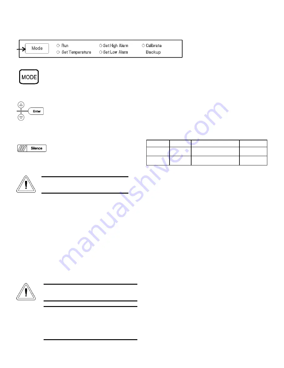
1.3 Operation of the Keypad
The 900 Series freezer has five basic modes
which allow freezer setup and operation. Press the
Mode key to scroll through the mode selections.
Up Arrow:
Increases or toggles the parameter
value.
Enter:
Must press Enter key to save to memo-
ry all changed values.
Down Arrow:
Decreases or toggles the param-
eter value.
Silence Key:
Press to silence the audible
alarm. See Section 4 for alarm ringback times.
1.4 Installing the Freezer
To remove the freezer from the pallet, use the 7/16"
wrench to remove all the bolts securing the shipping bracket to
the pallet.
Remove the shipping bracket. Remove the ramp boards
from the pallet and place the slotted end over the ramp brackets
on the pallet. The support blocks on the ramps will be facing
down. Before moving the freezer, make sure the casters are
unlocked and moving freely. Align the caster with the ramp
boards. Use adequate personnel to roll the freezer off the pallet.
The freezer can be easily pushed to the desired approved
location, described in Section 1.4.a. If necessary, the doors and
lower front panel may be opened to move the unit through tight
openings. When the freezer is in position, set the front caster
brakes.
a. Choosing the Location
Locate the freezer on a firm, level surface in an area with
an ambient temperature between 18°C and 32°C. Provide ample
room to reach the mains disconnect switch (power switch)
located on the rear of the freezer.
b. Installing the Wall Bumpers
The parts bag, located inside the cabinet, contains the fol-
lowing parts.
Install the bolts into the pre-tapped holes on the back of the
compressor section. Install a neoprene cap on each bolt. Refer
to Figure 1-2 for the locations of the pre-tapped holes.
c. Installing the Shelves
Install the shelf clips into the shelf pilasters (front and
back) at the desired shelf level. Install the shelves in the cabinet
onto the clips.
NOTE:
On units having the optional 5 inner door option, refer
to the instructions accompanying the inner door kit.
Model 900 Series ___________________________________________________________________Installation and Start-Up
1 - 3
If tipped more than 45°, allow the unit to set
upright for 24 hours before start up.
The freezer must not be moved with the product
load inside.
Quantity
Stock #
Description
Purpose
2
510016
1/4-20 x 5-1/2” Bolt
Wall Bumper
2
380520
Neoprene Cap
Cap Protector
For proper ventilation and airflow, a minimum
clearance of 5” at the rear and top and a clear-
ance of 8” on the side of the freezer is required.
Allow adequate space in the front of the freezer
for door opening.
Figure 1-7
Summary of Contents for 900 Series
Page 1: ...900 Series Forma 86C ULT Freezer Operating and Maintenance Manual Manual No 7010902 Rev 8 ...
Page 62: ......
Page 63: ......
Page 64: ......
Page 65: ......


